Download
1 / 13
3.02k likes | 6.82k Vues
By FLORENCE OCTAVIA PGT – PHY KV2 AFS, TAMBARAM. Alternating current generator. Definition:. Alternating voltage may be generated by rotating a coil in the magnetic field or by rotating a magnetic field within a stationary coil . The value of the voltage generated depends on

E N D
By FLORENCE OCTAVIA PGT – PHY KV2 AFS, TAMBARAM Alternating current generator
Definition: • Alternating voltage may be generated by rotating a coil in the magnetic field or by rotating a magnetic field within a stationary coil. • The value of the voltage generated depends on • Number of turns in the coil • Strength of the field • Speed at which the coil or magnetic field rotates
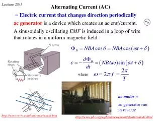
Principle E.M.I. (Electro magnetic induction) • When closed coil is rotated in a uniform magnetic field with its axis perpendicular to the magnetic field,the magnetic flux linked with the coil changes & an induced emf and hence current is set up.
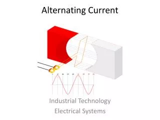
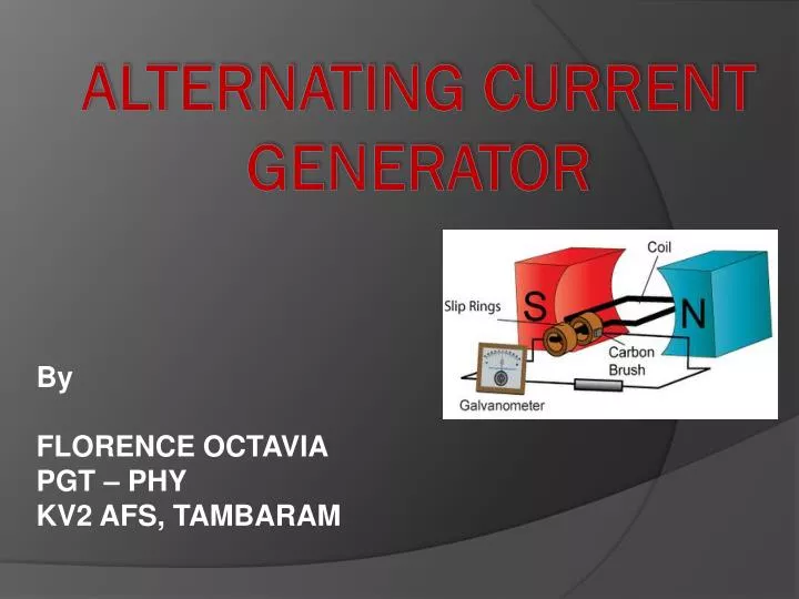
construction • Field magnet: A strong permanent magnet or an electro magnet. (N-S) • Armature: ABCD is a rectangular coil. Consists of a large no turns of insulated copper wire wound on soft iron cylindrical core It is rotated about an axis perpendicular to the magnetic field of the field magnet. • Slip rings: There are two brass rings connected to the two ends of the coil. As the armature coil rotates slip rings also rotate about the axis of rotation. • Brushes: Two graphite rods B1 and B2 remain fixed in their position but maintain sliding contact with slip rings and the current induced in the coil is fed to the external circuit through the brushes.
MAGNET ARMATURE RING BRUSH
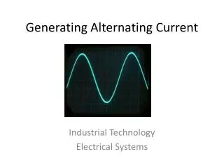
working • As the armature rotates the flux linked with it changes and so current is induced in it. • When the coil is rotated ,by Fleming’s RH rule current flows in one direction during the first half rotation of the coil. • During the second half rotation, the direction of current is reversed. • The direction of current is reversed after every half cycle. Hence ac is produced by the generator.
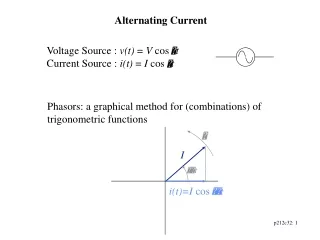
Expression for induced emf • Let N = no of turns in the coil A=face area of each turn B=magnitude of the magnetic field Ө=angle which normal to the coil makes with field B at any time t. ω=the angular velocity with which coil rotates.
Induced e.m.f • The magnetic flux linked with the coil with any time t will be ф= NBAcosӨ = NBAcosωt induced emf E = -dф/dt = -d(NBAcos ωt)/dt = NBAωsin ωt E=E0 sin ωt where E0 = NAB ω is the peak value of induced emf and the induced emf varies sinusoidally with time.