Download
1 / 22
230 likes | 309 Vues
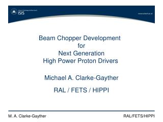
Beam Chopper R & D for Next Generation High Power Proton Drivers. Michael. A. Clarke-Gayther. RAL / ASTeC / HIPPI. Work Package 4 / RAL Progress Report for the period January 2004 – June 2005. Project planning / Overview:. Project planning / Detail:.

E N D
Beam Chopper R & D forNext GenerationHigh Power Proton Drivers Michael. A. Clarke-Gayther RAL / ASTeC / HIPPI
Work Package 4 / RAL Progress Report for the period January 2004 – June 2005 Project planning / Overview:
Fast and slowchoppermodules Chopper 1 (fast transition) BEAM Chopper 2 / Beam dump(slower transition) 5 M. A. Clarke-Gayther RAL/ASTeC/HIPPI
Phase 2 FPG system Dual polarity @ 1.4 kV max. High peak power loads Control and interface Power supply 9 x Pulse generator cards 9 x Pulse generator cards Combiner 9 x Pulse generator cards 9 x Pulse generator cards 7 M. A. Clarke-Gayther RAL/ASTeC/HIPPI
Table 1 Summary of measured performance parameters for the ‘Phase 2’ FPG systems
Slow chopper electrodes 16 close coupled ‘slow’ pulse generator modules Beam
SPG pre-prototype Breadboard system - 8 kV~ 5 μF LF cap.bank HVdamping resistor 8 kV push-pullMOSFETswitch + 8 kV~ 5 μF LF cap.bank + 8 kV~ 3 nF HF cap.bank - 8 kV~ 3 nF HF cap.bank Two turn load inductance ~ 50 nH Load capacitance ~ 30 pf 6 kV, 400 MHz ÷ 1000 probe Trigger input Auxiliary power supplies Cooling fan
Table 2 Summary of measured performance parameters for the ‘Breadboard’ SPG system
Timing schematic for the 201.25 MHz RAL FETS chopping scheme with a 4 kV (9 ns) SPG
Timing schematic for the 201.25 MHz RAL FETS chopping scheme with a 8 kV (12 ns) SPG
Timing schematic for the 324 MHz RAL FETS chopping scheme with a 4 kV (9 ns) SPG
Timing schematic for the 324 MHz RAL FETS chopping scheme with a 8 kV (12 ns) SPG
Table 3 FPG duty cycle and LF droop for the ESS and FETS schemes † Assumes 4 kV SPG with ~ 9 ns transition time (10 – 90 %) †† Assumes 8 kV SPG with ~ 12 ns transition time (10 – 90%)
The values of FPG pulse droop as shown in Table 3 should be used to predict the magnitude of the residual deflecting E-field acting on the un-chopped beam bunches.It is clear that for the case of a unipolar AC coupled FPG, the duty cycle dependent baseline shift and the low frequency cut-off dependent pulse droop will give rise to a residual deflection of the un-chopped beam, and that this deflection will be opposite in polarity to the deflection of the chopped beam. If we assume that the baseline shift is small, then some form of electronic compensation may be possible, but it should be noted that if a specific chopping scheme calls for variable duty cycle chopping, as in the ESS scheme, then the electronic compensation will be required to track the change in duty cycle.Cancellation of the residual beam deflection due to pulse droop may not be practical or indeed possible, and so it is clear that the resulting residual deflection of the beam must be included in beam dynamics simulations of chopper beam lines and linac ‘end to end’ studies.