Download
1 / 18
420 likes | 1.16k Vues
RESPONSE OF BASIC R, L, AND C ELEMENTS TO A SINUSOIDAL VOLTAGE OR CURRENT. By Sajid Hussain Qazi. RESPONSE OF BASIC R, L, AND C ELEMENTS TO A SINUSOIDAL VOLTAGE OR CURRENT.

E N D
RESPONSE OF BASIC R, L, AND C ELEMENTS TO A SINUSOIDAL VOLTAGE OR CURRENT By Sajid Hussain Qazi
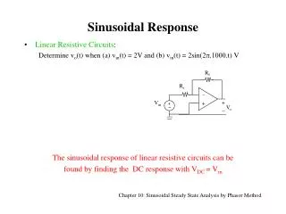
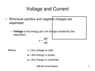
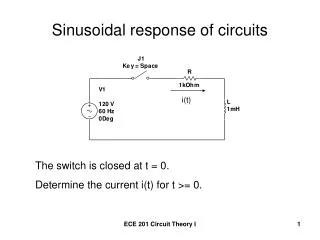
RESPONSE OF BASIC R, L, AND C ELEMENTS TO A SINUSOIDAL VOLTAGE OR CURRENT • As we are familiar with the characteristics of sinusoidal function, we can investigate the response of the basic elements R, L, and C to a sinusoidal voltage or current. • Here we will consider individually the effect of Sinusoidal voltage or current to Resistor, Inductor and Capacitor. • Also investigate their waveforms.
RESISTOR • For all practical purposes Resistor remain unaffected by the frequency of Power Line or the frequency of up to thousands KHz of the sinusoidal voltage or current. • For this frequency region, the resistor R of figure shown can be treated as a constant, and Ohm’s law can be applied as follows. For v= Vmsin ωt.
RESISTOR Where In addition to given value of I, Where
RESISTOR • For the plot of v and I, figure reveals... “For a purely resistive element, the voltage across and the current through the element are in phase, with their peak values related by Ohm’s law.”
PHASOR DIAGRAM for Resistive Element As we have found that in resistor voltage and current are in phase and their magnitudes are,
INDUCTOR • For the series configuration of, the voltage velement of the boxed-in element opposes the source e and thereby reduces the magnitude of the current i. • The magnitude of the voltage across the element is determined by the opposition of the element to the flow of charge, or current i.
INDUCTOR • As we know that the voltage across an inductor is directly related to the rate of change of current through the coil. • Consequently, the higher the frequency, the greater will be the rate of change of current through the coil, and the greater the magnitude of the voltage. • In addition, we also know that the inductance of a coil will determine the rate of change of the flux linking a coil for a particular change in current through the coil. • The higher the inductance, the greater the rate of change of the flux linkages, and the greater the resulting voltage across the coil.
INDUCTOR • The inductive voltage, therefore, is directly related to the frequency (or, more specifically, the angular velocity) and the inductance of the coil. • For increasing values of f and L, the magnitude of vLwill increase as described above. • Since vLwill increase with both ω( 2лf ) and L. FOR AN INDUCTOR So, by differentiation
INDUCTOR Therefore, OR Where, • If a phase angle is included in the sinusoidal expression for iL, such as, As VL is directly related to ω and L
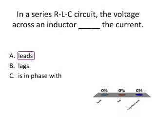
WAVEFORM AND PHASOR DIAGRAM for Inductive Element for an inductor, vL leads iL by 90°, or iL lags vL by 90°.
OPPOSITION ESTABLISHED BY INDUCTORto AC Supply • The opposition established by an inductor in a sinusoidal ac network can now be found by applying Eq. • For our purpose, • So, • The quantity qL, called the reactanceof an inductor, is symbolically represented by XL and is measured in ohms;
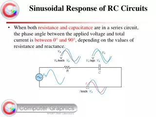
CAPACITOR • Let us now return to the series configuration where capacitor is the element of interest. • Our investigation of the inductor revealed that the inductive voltage across a coil opposes the instantaneous change in current through the coil. • For capacitive networks, the voltage across the capacitor is limited by the rate at which charge can be deposited on, or released by, the plates of the capacitor during the charging and discharging phases, respectively.
CAPACITOR • Since capacitance is a measure of the rate at which a capacitor will store charge on its plates, for a particular change in voltage across the capacitor, the greater the value of capacitance, the greater will be the resulting capacitive current. • In addition, the fundamental equation relating the voltage across a capacitor to the current of a capacitor [i=C(dv/dt)] indicates that, for a particular capacitance, the greater the rate of change of voltage across the capacitor, the greater the capacitive current.
CAPACITOR • Certainly, an increase in frequency corresponds to an increase in the rate of change of voltage across the capacitor and to an increase in the current of the capacitor. • The current of a capacitor is therefore directly related to the frequency (or, the angular velocity) and the capacitance of the capacitor. An increase in either quantity will result in an increase in the current of the capacitor. • Since an increase in current corresponds to a decrease in opposition, and iCis proportional to ωand C, the opposition of a capacitor is inversely related to ω( 2лf ) and C.
CAPACITOR • For capacitor, Since Therefore, Note that the peak value of iCis directly related to ω( 2 л f ) and C, as predicted in the discussion above.
CAPACITOR • A plot of vCand iCreveals that, for a capacitor, iCleads vC by 90°, or vC lags iC by 90°. If a phase angle is included in the sinusoidal expression for vC,
CAPACITOR • Applying, If the source current leads the applied voltage, the network is predominantly capacitive, and if the applied voltage leads the source current, it is predominantly inductive.