Download
1 / 54
540 likes | 725 Vues
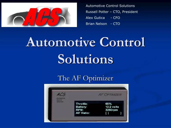
Automotive Control Solutions Russell Potter – CTO, President Alex Gutica - CFO Brian Nelson - CTO. Automotive Control Solutions. The AF Optimizer - An ENSC440 project -. Contents. The ACS Team The AF Optimizer The 440 project In-car Demo Now The future Conclusion Questions?.

E N D
Automotive Control Solutions Russell Potter – CTO, President Alex Gutica - CFO Brian Nelson - CTO Automotive Control Solutions The AF Optimizer - An ENSC440 project -
Contents • The ACS Team • The AF Optimizer • The 440 project • In-car Demo • Now • The future • Conclusion • Questions?
Automotive Control Solutions • A cutting-edge development team • specialize in control of automotive performance through electronic air/fuel optimization • Appeal to owners of any car, particularly older vehicles with simple electronic control
Who Are We? • User Interface Firmware Lead • Russell Potter • DSP Firmware Lead • Alex Gutica • Hardware Lead • Brian Nelson
Internal Combustion Engine • Requires a correct mixture of fuel and air in order to function • Fuel is mixed with the air, compressed, and ignited. • When ignited, the air/fuel mixture drives pistons down, which turns a crankshaft.
Fuel Delivery • The most efficient burn mixture has an 14.7:1 air-fuel ratio. • The lean condition • The air-fuel ratio is too high • Results in detonation, power loss, increased emissions • The rich condition • The air-fuel ratio is too low • Results in reduced economy, increased emissions, power loss
Fuel Injection System • Proper fuel delivery is electronically controlled through a fuel injection and ignition timing system
Fuel Delivery • Based on a 2-variable present map in the ECU • Load/Airflow meter • RPM
The Problem • Fuel maps and fuel delivery are designed for compromise • By modifying fuel delivery and consequently air-fuel ratios, improvements can be made • Performance • Economy • Improved Emissions
Why Modify an Already “Tuned” System? • Are the original engineers incompetent? • No but, the original characteristics of the motor can be changed • Performance enhancements • Changing the amount of air\fuel flowing into the motor • General engine wear • Perhaps a different “compromise” is desired
Current Solutions for Modifying Air-Fuel Ratios • Modifying the computer: new fuel maps • Model-specific • Costly • Lack of user-specific ability to tune • Standalone systems • Complete computer replacement is very intrusive • Requires extensive, expensive tuning • Mechanical solutions • Rudimentary • APEXi SAFC • Our direct competition
The AF Optimizer • Its functionality and potential market • Its competitive edge • Features • System Design and Implementation • Hardware and firmware
What does it do? Recalibrates air flow sensor data, while monitoring car Allows for flexible tuning of air fuel ratios Moves to different location on original fuel map Monitors automobile sensors with real-time visual display to users Why would one buy it? To inexpensively and safely optimize delivery of fuel to their engine The AF Optimizer
Target Market • Customer needs to tune their fuel system • Desires better performance • Wants a simple, noninvasive install • 29 Billion Dollar aftermarket part industry • Our target demographic is young people • With older cars • Who demand an inexpensive, feature packed fuel control system
Compatibility • Compatible with wide range of manufacturers • Required: • Fuel injection • MAP or VAF sensor • 0-5V Scale • Reality: Older, simple computer is better
AF Optimizer Advantages • First and foremost, price • Versatile for use on many different vehicles • Easy to install and remove • Un-intrusive to the vehicle • Real-time monitoring • Works on older cars
Feature Overview • Airflow tuning features • Shift Light Features • Monitoring Features
Tuning Features • Many Tuning points provides more tunability • based on RPM and Throttle % • RPM Tuning • 2000-8750 RPM - 250 RPM increments • 75% to 125% - 1% increments • Linearly Interpolates between tuning points 3000 3250 3500 3750 >102% 110% 109% 107% 98% 100% 97% 98%
Tuning Features • Throttle Percentage Tuning • 2 Calibration Curves: High / Low Throttle • User defined - based on throttle % thresholds • Throttle Thresholds • Low: e.g. <30% throttle • High: e.g. >90% throttle • Linearly interpolates between the thresholds
Tuning Features • Overall: 2-Dimensional interpolation • RPM and Throttle % are variables
Shift Light Features • 2000-10000 RPM in 100 RPM increments • 5 Sequentially lit LEDs • LEDs light up every 100 RPM as you approach your desired shift point • Increasing brightness • Example where shift light set to 5000 RPM
Monitoring Features • Real-time monitoring of engine’s sensors • RPM • Throttle % • Battery Voltage • O2 Sensor Voltage • Airflow and calibration monitoring • Calibration % • Pre and Post Airflow Voltages RPM: 3250rpm Throttle: 80% Battery: 14V O2 Sensor: 220mV Airflow: 106% Pre: 2050mV Post: 2184mV
RPM Sensor ECU Throttle Sensor AF Optimizer Airflow Sensor Component and System Layout System Overview
AF Optimizer: Hardware • Part Sourcing • PIC 16F Microcontroller • Maxim 10-bit DAC • Noritake 4-line x 20 character VFD • 5Volt Regulator • Input Circuitry
Hardware Challenges • PIC Microcontroller • Need to service the display, inputs and DAC fast • Fast speed for calculations • DAC Accuracy • Power Management • I/O conditioning • Noisy car signals, voltage scaling • Creating a stable, fast analog output with DAC
AF Optimizer: Firmware • Performed two functions • Sample inputs, calculate, output • Handle interaction with user • Buttons • Display • Written in C • High level functionality • Easy writing, debugging • Memory & Processor Usage
Firmware Challenges • Debugging and Simulation • Simulator has limited functionality • PIC was new to us • Timing • We had strict timing demands • Needed all three hardware timers • Required very careful time management
Final Product Performance 1 • Successful integration into the vehicle was dependent upon system response speed • Response to a 16Hz sine as airflow input (unrealistic, but illustrates system performance)
Final Product Performance 2 • A more realistic response to a square wave • 1.5 ms system delay • Small capacitor used to eliminate discontinuities
Integration Challenges • Very smooth integrating into the car • Research of sensor signals • In-car signal testing with oscilloscope • Great lab setup for proper simulation • Start up and Connection issues • Starter draws current and dropped the battery voltage • FIX: Cap and diode • Bad connections with breadboard and car wiring • FIX: Soldered car wiring harness & PCB • Car has a bad O2 Sensor
Demo Time • Things to demonstrate: • Monitoring • How to setup throttle values • Shift light • How to set airflow calibrations • Car running and driving • Out to B-LOT everyone
Dyno Results • Very Impressive Results!! • Running too rich loses power. • Running too lean loses power… • We are able to change the air fuel ratios • Here are the results
Rich Run • Tried 120% but threw Check Engine Light • Tuned to 110% from 2000-6700 RPM (redline) • Results:
Lean Run • Running too lean lost power in low RPMs • Original ECU runs too rich at high RPMs • Use AF Optimizer to lean high RPMs • Results:
Engineering Considerations • Positive system feedback due to vehicle velocity • Does not affect airflow into engine • Dynamometer is appropriate for vehicle tuning • System memory considerations (derivatives) • Precautions were taken to prevent derivative reversal • Airflow signal adjustability range limited to 75% - 125% • High and low throttle curves at least 20% of entire throttle range apart • Testing indicates airflow signal changes much faster than throttle
Budget • Proposed Budget: $665 • Actual Spending: $200 • Difference: $-465 • Summary We UNDERSPENT! Due to building only 1 prototype, cheap dyno time
AF Optimizer: Schedule • Predicted Completion Dates • February 27 • March 6 • March 13 • March 24 • Actual Completion Dates • March 15 • March 6 • March 17 • April 4 • Firmware: • Hardware: • System Integration: • Final Testing:
AF Optimizer: Now • Have a fully functional prototype! • We’ve priced many parts in quantities • The display dominates • Accounts for as much cost as all others combined • Produced prototype PCB and casing • Plans underway for production model • Designed to use 1 PIC for cost
AF Optimizer: The Future • Small distribution at first • Use online car clubs for marketing • Will hopefully get feedback • If all goes well, incorporate! • Outsource manufacture to overseas • Build relationships with distributors • Maybe make a few $$
Future Design Considerations • Split it up into modules • Display and buttons • Main PC Board and wiring to car’s wiring • Shift light (remotely mounted) • Optimize PCB designs
ACS Team Summary • This was a great learning experience • Conclusions • Acknowledgements