Download
1 / 38
400 likes | 454 Vues
Briefing for Flight Test Safety Workshop May 2008 John Siemens, P.E. Sr. Mgr. Flt Operations Chief Test Pilot. The SJ30-2 Airplane. Certified Part 23 Commuter Category with Special Conditions equivalent to Part 25 Aluminum Construction with some non-structural composites Full span LE Slats

E N D
BriefingforFlight Test Safety WorkshopMay 2008John Siemens, P.E.Sr. Mgr. Flt OperationsChief Test Pilot
The SJ30-2 Airplane • Certified Part 23 Commuter Category with Special Conditions equivalent to Part 25 • Aluminum Construction with some non-structural composites • Full span LE Slats • Max Operating Altitude – FL490 • Range – 2500 nm • VMO / MMO – 320 KIAS/0.83 • Pressurization – 12 psi • Single Pilot Qualified
Overall Test Program • SN002 – Lost in Accident • SN003 – Systems (Hydraulics, Electrical, Engines, Fuel, Autopilot, Anti-ice • SN004 – Aerodynamics, S&C, Flutter, Performance, Continued Safe Flight after Failures, Ice Shapes • SN005 – Avionics, Interior, F&R, Flight Standards Board
The Reason ModelDeveloped by Prof. James Reason Defenses or Barriers (Processes) Weaknesses in Defenses or Barriers (Holes in Processes) Does Your Cheese Need to be Moved? Accident Trajectory (Chain of Events) Blocked (Chain Broken) The holes did not line up Scene of the Incident / Accident The Greater the Number of Defenses or Barriers (Processes) the Less Likely the Holes Will Line Up
Defenses and Barriers(Adding Barriers) Flight Test • Sequence of Test Program • Roadmap to Success • Experience Level of Personnel • What level of experience is required to fly the test? • Experience level of Test Plan author? • Safety Program (FAA Order 4040.26A) • TRB / SRB / FRR • Who participates • Test Hazard Analysis • At what level of the Company are Safety Decisions Made? • Routine Safety Meetings and Reviews • “Knock-It-Off” Criteria Established • Where will the tests be accomplished? • Flight Test Policies and Procedures • Crew Rest Requirements • Health and Fitness Requirements • Experimental Aircraft Configuration Control • Pilots briefed on configuration before every flight • Temporary Test Aircraft Limitations (TTAL) Culture
Defenses and Barriers(Misaligning the Holes) • High Risk = High Level Decisions • Acceptance of high risk is a Company decision Risk Mitigation • Design Technical Reviews • Safety Reviews • System Safety Analysis • Weather • Test Location • Knock-it-off Criteria • Ground Safety Equipment • Road map • Checklists • Experience • Training • Personal Safety Equipment • Instrumentation • Pilot Display Information • Number of crewmembers • Telemetry • Communications • Chase Aircraft • Emergency Recovery System • Design • System Test • Location of Controls • Checklist Items • Emergency Procedures • Practice • Egress System • Design • System Test • Location of Controls • Checklist Items • Emergency Procedures • Practice
Safety Reviews(Finding the Holes in the Plan) Does everyone understand the process? • Technical Review Board (TRB) • Review of applicable technical design details • Independent assessment of technical soundness of the test plan • Initial identification of flight test associated risks • Safety Review Board (SRB) • Chaired by the Flight Safety Officer (FSO) • Review of the flight test program planning • Final approval of the Test Plan and Test Hazard Analysis Worksheets • Critique of the teams planning effort • Flight Readiness Review (FRR) • Final Management Review • Answers the question, ”Are we ready to test?” • Ensures “action items” from TRB and SRB have been completed
Test Hazard AnalysisDefines Pilot Experience Required to Fly the Test Test Category A B C Pilot Experience Sr. Eng Specialist TP PIC PIC PIC Eng Specialist TP PIC PIC PIC Sr. Engineer TP SIC PIC PIC Engineering TP SIC SIC PIC Jr. Engineering TP N/A SIC SIC
Policies and Procedures • Engineering Procedures • EP-005 “Experimental Aircraft Release Procedures” • EP-006 “Flight Test Work Order (FTWO) Procedures” • EP-007 “Release and Acceptance of Aircraft for Test” • EP-008 “Temporary Test Aircraft Limitations Procedures” • EP-051 “Exp Aircraft Config Mgmt and Conformity” • Flight Operations Policies and Procedures • FOP-001 “Flight Operations Policies and Procedures” • FOP-002 “Production Flight Test Policies and Procedures” • FOP-003 “Pilot Training Policies and Procedures” • FOP-004 “Engine Run and Taxi Qualification Training” • FOP-005 “Ground Test Safety Procedures” • FOP-006 “Approval of Airplane Flight Manuals, Checklists and Supplements” • FOP-007 “Approval of AFM Temporary Change Notices” • FOP-008 “SSAC Minimum Pilot Requirements” • FOP-009 “Engineering Flight Test Safety Program” • FOP-010 “Operations in RVSM Airspace” • FOP-011 “Engineering Flight Test Experimental Aircraft Scheduling”
Design Improvements • New prototype (no asymmetric wing twist) • High Speed Wind Tunnel tests • Added 5 VG’s to upper wing surface • Energized airflow over wing • Moved speed brakes outboard • +1.5 G’s when deployed at MMO • Aileron Thick TE reduces hinge moment
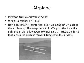
SJ30-2 Airspeed Envelope 49,000 Ft Mdf = Mach 0.90 Mmo = Mach 0.83 Altitude 28,300 Ft Vdf = 372 KCAS Vmo = 320 KCAS Airspeed
Weight Altitude Airspeed Center of Gravity +G’s Normal Acceleration Velocity V-N Diagram -G’s Know Which Envelopes are Being Pushed Stability & Control Airspeed Calibration? Burt Rutan’s White Knight
SJ30-2 Flight Flutter Program • Airspeed Calibration Complete To VMO/MMO • CG Envelope Defined • Aerodynamic Configuration Defined • Aircraft Conformed to Type Design • Stall Tests Complete • Stability and Control Tests Complete • FAA Approved Test Plan • Accelerometers Installed & Calibrated • Telemetry System • Egress System Installed & Tested • High Speed Chute Installation • Chase Aircraft • Unusual Attitude Training Completed • Egress Training Completed • Technical Review Board • Safety Review Board • Flight Readiness Review Mojave, CA June – July 2004
Acceptance Requirements • Flutter free to VDF and MDF • Statically stable in all three axes • No mach buffet at speeds up to MMO • At speeds above MMO buffeting not severe enough to cause control problems • Able to generate 1.5G’s normal acceleration on recovery
Aircraft Instrumentation Roll, Pitch, Yaw Angles Roll, Pitch, Yaw Rates Roll, Pitch, Yaw Forces Control Surface Deflections Boom Altitude & Airspeed Ships Altitude & Airspeed Accelerometers Strain Gages Co-pilot Video Screen Pedal forces Force wheel On-board computers Observers data station
Telemetry Data Station Tracking Antenna Eric Kinney Co-Pilot Monitors Data Strip Charts David Wells Telemetry Instrumentation Mario Asselin Aerodynamics
High Speed Recovery Chute System Control on Aft End of Center Pedestal Chute Arming Chute Deployment Chute Jettison Chute Design: 4000 lbs drag at 400 kts @ 10,000 ft Structural Design: 4000 lbs limit load 6000 lbs ultimate load
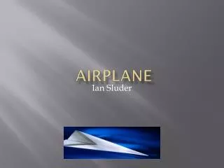
DEPLOY ROCKET STEEL WELDMENT STINGER BOOM ACCESS PANEL CHUTE CANISTER Chute Design LATCH ACTUATOR MICROSWITCH JETTISON CUTTERS LWR RISER FERRULE KEVLAR “LOAD LINE”
Dive Angles 12.5 deg ND
Drag Chute Deployment Test • “Jerk” feel on deployment • Roll , Pitch and Yaw during deployment • Deceleration Rate • Ability to maintain level flight with chute deployed • Chute Oscillation After Deployment • Controllability • Jettison • Roll, Pitch and Yaw on Release
Egress System Cabin Pressure Dump (6psi) Door Jettison
Egress Training Both pilots belted in and connected to aircraft Seats positioned for flight Door installed and rigged Practice until: Evacuation of aircraft could be accomplished in 20 seconds Each pilot knew his sequence steps so as to not interfere with the other
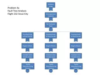
25k - 33k ft • AR Weight, • Mid CG • Long Stab. Assess. • Lat. Dir. Stab. Assess. • Flutter • Chase above 0.85M • 0.86M, 0.87M & • 0.88M are individual flights 3 24 Test Points A/S = 0.78M, 0.80 M 0.82M, 0.83M 0.84M, 0.85M 0.86M, 0.87M 0.88M • Technical Review Boards • Chute & Egress Systems • Aero Conformities • Aerodynamic Review • Systems • High Speed Envelope Program • Safety Review Board • Egress System Validation • Chute Deployment & Jettison Validation • Return to Service • Telemetry Check Flight • Vibration & Buffet testing (≤Mmo/Vmo) • 15k-21k ft • AR Weight, • Mid CG • Long Stab. Assess. • Lat. Dir. Stab. Assess. • Flutter • Chase above 340 KCAS • 368 KCAS & 372 KCAS • are individual flights • 41k-47k ft • AR Weight, • Mid CG • Long Stab. Assess. • Lat. Dir. Stab. Assess. • Flutter • Chase above 0.85M • 0.86M, 0.87M & 0.88M • are individual flights Flight Readiness Review Start of High Speed Envelope Testing 1 2 17 Test Points 17 Test Points A/S = 320 KCAS 340 KCAS 350KCAS 360 KCAS 368 KCAS 372 KCAS A/S = 0.83 M 0.84M 0.85M 0.86M 0.87M 0.88M DATA ANALYSIS & SRB for Considerations of Further Envelope Expansion
AR ALT • AR Weight, • Aft CG • Long Stab. Assess. • Lat. Dir. Stab. Assess. • Flutter • Light Fuel Points (2) • YD OFF Points (3) • AR ALT • Lgt. Weight, • Aft CG • Upset Maneuvers • 25k - 33k ft • AR Weight, • Mid CG • Long Stab. Assess. (0.89) • Lat. Dir. Stab. Assess. (0.88) • Flutter (0.88) • 41k - 47k ft • AR Weight, • Mid CG • Long Stab. Assess. (0.89) • Lat. Dir. Stab. Assess. (0.88) • Flutter (0.88) 5 4 5 4 18 Test Points 19 Test Points 3 Test Points 3 Test Points CONTINUE EXPANDING HIGH SPEED ENVELOPE PAST 0.88?? NO YES DATA ANALYSIS & SRB for Considerations of Further Envelope Expansion End of Envelope Definition
AR ALT • AR Weight, • Aft CG • Long Stab. Assess. • Lat. Dir. Stab. Assess. • Flutter • Light Fuel Points (2) • YD OFF Points (3) • AR ALT • Lgt. Weight, • Aft CG • Upset Maneuvers • 41k - 47k ft • AR Weight, • Mid CG • Long Stab. Assess. (0.90) • Lat. Dir. Stab. Assess. (0.89) • Flutter (0.89) • 25k - 33k ft • AR Weight, • Mid CG • Long Stab. Assess. (0.90) • Lat. Dir. Stab. Assess. (0.89) • Flutter (0.89) 6 7 6 7 1 8 Test Points 19 Test Points 3 Test Points 3 Test Points CONTINUE EXPANDING HIGH SPEED ENVELOPE PAST 0.89?? NO YES End of Envelope Definition
AR ALT • AR Weight, • Aft CG • Long Stab. Assess. • Lat. Dir. Stab. Assess. • Flutter • Light Fuel Points (2) • YD OFF Points (3) • AR ALT • Lgt. Weight, • Aft CG • Upset Maneuvers 8 9 18 Test Points 19 Test Points End of Envelope Definition
Test Point Sequence • Altitude sequence was: • Low – dynamic pressure effects only • High – mach effects only • Critical (@ VMO/MMO knee) – combined Q and Mach effects • Three dives were made to clear each speed increment during the speed envelope expansion • Airspeed verification with chase and general controllability • Static Lateral, Directional and Longitudinal stability • Control Raps for flutter (elevator, aileron, rudder) in both directions
Abort (Knock-it-Off) Criteria • Within Planned Flight Region • Lateral control authority (50 lb wheel force) capable of handling FAR lateral gust criteria • Lateral control authority (50 lb wheel force) capable of handling 160 lb pedal force • Minimum 20 deg/sec roll rate capability (with 50 lb wheel force) • Excursion Exceeding Planned Flight Region • Account for at least Mach 0.03 over-speed from planned test conditions • Lateral control authority (75 lb wheel force) capable of handling FAR lateral gust criteria • Lateral control authority (75 lb wheel force) capable of handling 160 lb pedal force • Minimum 20 deg/sec roll rate capability (with 75 lb wheel force) • Conditions Require Termination of Flight for Data Analysis and Review • Lateral stability at neutral or unstable • Extrapolated flight test roll control authority was not met • Unable to trim aircraft hands-off laterally and directionally • Airspeed and Mach calibration deviate from extrapolation
Test Protocol • Flight crew calls “On Condition” • Chase calls “In Position” • Ground verifies ground station is ready and calls “Go for condition” • Flying FTE reads speeds during the dive (instrumentation has a hot audio link) • Ground test director monitors airspeed and altitude readout and verifies speeds to flight crew during descent. Ground calls “Stop Test” when test aircraft is within 1000 ft of minimum test altitude. • Anyone can call abort for the test condition by calling “Abort, Abort, Abort” • Test aircraft will immediately abort the condition by pulling throttles to idle, extending speed brakes and inducing a positive 1.5 G pull • If the test needs to be discontinued for any reason other than a safety reason (such as loss of TM or a strip chart malfunction) the Ground Station will call “Stop Test” • Test aircraft will stop the test by pulling to a positive 1.5 G’s and reducing power and using speed brakes as needed. • Flight crew will call “Test Complete, Under Control” when the test aircraft is recovered to a safe flight condition.
Loss of Control Protocol • Flight crew will immediately deploy the high speed recovery chute. • Chase will call “Chute Deployed” • If the test aircraft fails to respond to the recovery chute by 18,000 feet for Md tests or 10,000 ft for Vd tests, chase will call “Bailout, Bailout, Bailout” • Chase will follow the aircraft and verify to the Ground Station when the door has been jettisoned and the crew are out of the aircraft. • Chase will loiter in the area and guide ground rescue to the site. • Test crew will have personal ELT’s and com radio’s for communication to rescue crews.
Phase I Summary of Testing • 9-27 June 2004 (19 Days) • 32 Flights in 16 Flight Days • 50.7 Flight Hrs • Averaged 2.00 flights/day • Averaged 1.58 hrs/flight • Tests Accomplished • Vibration and Buffet Margins • Static Lateral / Directional Stability • Static Longitudinal Stability • Longitudinal Maneuvering Stability • Flight Loads • 305 Test Conditions
Phase II Summary of Testing • 7 July – 1 August 2004 (26 Days) • 40 Flights in 18 Flight Days • 62.0 Flight Hrs • Averaged 2.22 flights/day • Averaged 1.55 hrs/flight • Tests Accomplished • Dynamic Lateral / Directional Stability • Dynamic Longitudinal Stability • Longitudinal Control • Lateral / Directional Control • HS Envelope Expansion • Aeroelastic Stability (Flutter) • HS Upset Maneuvers • HS Stability and Control • 366 Test Conditions
Data Strips M 0.90 Mach No. 36,000 ft Altitude 10,500 fpm 27,000 ft Pitch 12 deg ND 1.9 G’s G’s
Wing Anti-Ice Failure Ice Shape Stall Tests Aft CG, Heavy Weight 26 January 2005, Roswell, NM
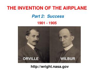
45 min radome Wing Anti-ice Failure 9 min shape 45 min wing tip 45 min pylon LE 45 min V-tail At aileron/flap wing span location 45 min H-tail tip 2 min delayed activation Wing Failure Ice as Installed vs Design • The as installed shape, with the misfit due to the double sided tape and extra thickness of the oil dry, is approximately 25% bigger than the minimum requirements. As installed (red) Design (blue)