Download
1 / 15
150 likes | 155 Vues
This critical design review discusses the modifications made to the LO system in the KFPA prototype testing, including frequency range expansion and power specification changes.

E N D
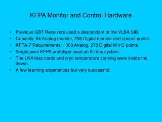
KFPA LOModifications (from single pixel results)Critical Design Review January 30, 2009 G. Anderson
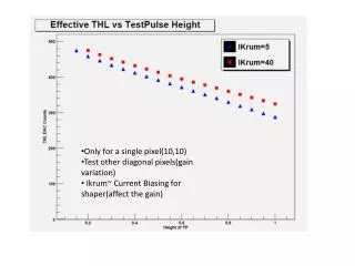
Concerns • Several issues were raised during single-pixel KFPA prototype testing with regard to the LO system: • Why does the output power fall off rapidly at the band edges? Can we increase the frequency range of the 1st LO output? • Should the output power specification be modified? • Should additional spectral purity requirements be added to the specification? KFPA LO Critical Design Review, January 30, 2009
Original Requirements • Two local oscillator sources (HP/Agilent 83620 synthesizers that generate up to 20 GHz) are available in the GBT receiver room. The original specification called for the following to be supplied to each of 7 Downconverter modules: • LO1: • 25.7 to 32.4 GHz • At 25.7 GHz, -2 dBm (+/- 5 dBm) • At 32.4 GHz, -4 dBm (+/-7 dBm) • A gain slope of -0.3 dB/GHz at the mixer input would give nominal levels. • LO2: 8.9 GHz @ +3 dBm (+/- 5 dBm) KFPA LO Critical Design Review, January 30, 2009
Original Requirements • No spectral purity specification was imposed. However, a self-imposed specification of 30 dB rejection of the third harmonic of the 1st LO input signal (as provided by the 83620 generator) seemed reasonable and was used as a design guide. • The following are slides from the Conceptual Design Review giving the schematic of an LO Distribution Module. One module will supply LO power to all 7-pixels. (one output is not used and is terminated) KFPA LO Critical Design Review, January 30, 2009
LO Distribution Module (High Frequency Side) 3dB Output (each): - 1 dBm 3dB Input: 12.85 - 16.2 GHz 3dB +7 dBm (from LO Driver Module) 3dB X2 BPF 3dB 3dB Hittite Loss = 3dB HMC578 1.5 dB (Active Multiplier) MAX Output +17 dBm for +4 dBm drive 3dB 3dB 3dB KFPA LO Critical Design Review, January 30, 2009
LO Distribution Module (Low Frequency Side) 3dB Each Output: +4 dBm 3dB 8.9 GHz - 1.5 dBm 3dB (from LO Driver Module) +17.5 dBm 3dB 3dB Hittite 3dB HMC451 Gain = 22 dB Output IP3 = +32 dBm 3dB NF = 7 dB 3dB 3dB KFPA LO Critical Design Review, January 30, 2009
Single Pixel Testing • Single-pixel tests were performed using a test fixture consisting of the multiplier and bandpass filter shown in the schematic (LO Distribution Module (High Frequency Side)) above. • Tests showed the following problems: • The LO multiplier output dropped off sharply outside the original frequency range. • During test, the LO drive desired for the input of the downconverter was significantly higher than called for by the LO1 specification. • A spur was detected at the noise floor during a one minute integration. Its frequency indicated that one of the mixing inputs that created it was the LO1 input to the x2 multiplier. This was verified during test when an improvised high pass filter (waveguide) was added to the x2 output and the spur disappeared. KFPA LO Critical Design Review, January 30, 2009
Corrective Action • The multiplier output filter was originally designed around the initial specification. The original bandwidth was kept as narrow as possible to improve the 3rd harmonic rejection and to give some margin to allow for manufacturing tolerances. KFPA LO Critical Design Review, January 30, 2009
New Filter KFPA LO Critical Design Review, January 30, 2009
Specification Change • LO1: • 24.8 to 34.3 GHz • At 24.8* GHz, -5 to +3 dBm • At 34.3* GHz, -3 to +4 dBm • Specified differently at upper and lower band edges to allow a positive gain slope. This will largely counteract the negative gain slope from cables. • LO2: 8.9 GHz @ +3 dBm (+/- 5 dBm) KFPA LO Critical Design Review, January 30, 2009
The wider LO1 frequency range will allow operation over the sky frequency range of 18.0 to 27.5 GHz. The minimum power levels to be applied to the Down-Converter Module were also increased. KFPA LO Critical Design Review, January 30, 2009
High Pass Filter • The original plan was to add a high-pass filter to the multiplier output. • The spurious output that drove this addition was at the noise floor for a 1 minute integration. • Discussion with T. Minter and J. Lockman revealed that the maximum integration time one could ever expect was 1000 hours……worst case. • The reduction to the noise floor would be proportional to the square root of the ratio of integration time…..yielding a reduction in the noise floor of 23.9 dB. KFPA LO Critical Design Review, January 30, 2009
Bandpass Filter • Instead of adding a high pass….why not cascade another bandpass filter? • Still reduces the feedthrough of any x2 fundamental. • Adds additional rejection to any x3 multiplier output. • Why not increase the number of poles of the original filter? • We already have greater than 50 dB rejection of the x2 input. • Approaches ultimate rejection of the filter where stray coupling dominates. KFPA LO Critical Design Review, January 30, 2009
New Amplifier • The addition of the high-pass filter and the change in the output power specification forced the addition of an amplifier to the multiplier output. The large attenuators placed at the input and output serve two functions: • to lower the amplifier input power • to mask the input and output return loss of the amplifier (output return loss is 6 dB). KFPA LO Critical Design Review, January 30, 2009
Final Version LO Distribution Module(High Frequency Side) 3dB Output (each): 1 dBm* 3dB Input: 12.4 -17.15 GHz +7 dBm (from LO Driver Module) 3dB 3dB BPF X2 BPF 3dB 3dB 3dB 3 dB Hittite HMC283 Amplifier +21 dB gain 10 dB Loss = 2 dB MAX 3dB Loss = 2.0 dB MAX Hittite HMC578 (Active Multiplier) Output +17 dBm for +4 dBm drive 3dB 3dB 3dB KFPA LO Critical Design Review, January 30, 2009