Download
1 / 22
220 likes | 374 Vues
UCD. Yong Choi BPA. What is UCD?. A use case is a set of scenarios that describing an interaction between a user and a system . What a system does…rather than how a system does A use case diagram displays the relationship among actors and use cases .

E N D
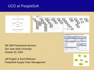
UCD Yong Choi BPA
What is UCD? • A use case is a set of scenarios that describing an interaction between a user and a system. • What a system does…rather than how a system does • A use case diagram displays the relationship among actors and use cases. • The two main components of a use case diagram are use cases and actors.
Actor and Use Cases • An actor represents a user or another system that will interact with the system you are modeling. • A use case is an external view of the system that represents some action the user might perform in order to complete a task.
When to Use: Use Cases Diagrams • Use cases are used in almost every project. • The are helpful in exposing requirements and planning the project. • During the initial stage of a project most use cases should be defined, but as the project continues more might become visible.
How to Draw: Use Cases Diagrams • Use cases are a relatively easy UML diagram to draw, but following is a very simplified example. • The example is only meant as an introduction to the UML and use cases. If you would like to learn more see the Resources page for more detailed resources on UML.
Example • Start by listing a sequence of steps a user might take in order to complete an action. For example a user placing an order with a sales company might follow these steps. • Browse catalog and select items. • Call sales representative. • Supply shipping information. • Supply payment information. • Receive conformation number from salesperson.
Source: http://atlas.kennesaw.edu/~dbraun/csis4650/A&D/index.htm
Another Simple Example • A patient calls the office to make an appointment (or cancel an appointment), The receptionist finds the empty time slot in the appointment table and schedule the appointment (or cancel the appointment).
What to put in the "System" box? • In the diagram below we would like to represent the use cases for a camera. Suppose we choose "Open Shutter", "Flash", and "Close Shutter" as the top-level use cases. Certainly these are all behaviors that a camera has, but no photographer would ever pick up their camera, open the shutter, and then put it down, satisfied with their photographic session for the day. The crucial thing to realize is that these behaviors are not done in isolation, but are rather a part of a more high-level use case, "Take Picture". (Note that it does make sense for a photographer to "Take Picture" just once during a session with their camera.)
The actors in my diagram have interactions. How do I represent them? • Suppose you wanted to diagram the interactions between a user, a web browser, and the server it contacts. Since you can only have one system on the diagram, you must choose one of the obvious "systems", such as the server. You might then be tempted to draw interaction lines between the actors, but this is a problem because it isn't clear what the interaction means, so it isn't helpful to show it here. A more useful solution would be to draw two diagrams, showing all of the interactions.
How is a UCD different from a traditional flow chart? • UCDs are meant to be a top-down, horizontal description of functionality • if functionality or behavior is added or deleted over the life of your project, the scope of the change you need to make is proportional to both the scope of the change in the system itself, and the maturity of your model. • This is useful because it means that when your model is very young (only high-level diagrams drawn) making sweeping changes to the system does not involve throwing very much work away.
How is a UCD different from a traditional flow chart? • A flow chart does not correctly describe the system until you have finished drawing it, and even then small changes in the system will result in significant reworking of your flow charts. • Complex logic: Sometimes, the program logic is quite complicated. In that case, flowchart becomes complex and clumsy. • Alterations and Modifications: If alterations are required the flowchart may require re-drawing completely. • Reproduction: As the flowchart symbols cannot be typed, reproduction of flowchart becomes a problem. • The essentials of what is done can easily be lost in the technical details of how it is done.
When do I use the uses arrow? • Suppose you wanted to add detail to the diagram shown below, representing an airline reservation system. First, you would create a separate diagram for the top-level services, and then you would add new use cases that make up the top-level ones. There is a uses edge from "Check in Passenger" to "Weigh Luggage" and from "Check in Passenger" to "Assign Seat"; this indicates that in order to Check in a Passenger, Luggage must be Weighed and a Seat must be Assigned. Similarly, the diagram indicates that in order to add a reservation to the system, the available space must be checked and the passenger's information must be recorded. You could imagine breaking these use cases down further to show more detail.
When do I use the extends arrow? • Suppose you wanted to add detail to the diagram shown below, representing an airline reservation system. Specifically, what you would like to show is that not all of the seats aboard the airplane are exactly alike (some window and some aisle seats), and sometimes passengers will express a preference for one of these types of seats but not the other. But of course, they cannot just be given their preference right away, because the seat they want might not be available. Therefore, the process of assigning a window seat involves checking for the availability of window seats, whereas the process of assigning an aisle seat involves checking for the availability of aisle seats. But even though these processes are different, they are quite similar in a number of other ways, so it doesn't make sense to ignore their similarities. Fortunately, UML lets us have both: we write that assigning these two types of seats are different processes, but they are similar in that both processes extend a common, more general process (assigning seats.)