Download
1 / 8
80 likes | 158 Vues
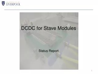
Ge 31/10/03. First thermal measurements on modules on stave. M.Dameri, F.Vernocchi et al. (R. Cereseto, G.Gariano, C.Gemme, M. Parodi, C. Pizzorno, L.Rossi, A.Rovani, E.Ruscino). 3 FEI1 modules: 20210020420058 in position 3, power: 3.3W (chip7 off, chip8 malfunctioning)

E N D
Ge 31/10/03 First thermal measurements on modules on stave M.Dameri, F.Vernocchi et al. (R. Cereseto, G.Gariano, C.Gemme, M. Parodi, C. Pizzorno, L.Rossi, A.Rovani, E.Ruscino) 3 FEI1 modules: 20210020420058 in position 3, power: 3.3W (chip7 off, chip8 malfunctioning) 20210020420026 in position 4, power: 2.4W (chip14 off) 20210020420023 in position 11, power: 2.5W (chip 8&13 off) have been mounted on a prototype stave with the production machine and procedure. Thermal images have been taken with the module fully configured and with a power consumption as detailed above. Cooling was done circulating fluid at ~10C in a room temperature environment.
chip7 chip0 Tntc=120C 20210020420023 no power High digital current on pigtail Tntc=17.50C 20210020420023 power on
Tntc=130C 20210020420026 no power Tntc=16.50C 20210020420026 power on
Tntc=12.60C 20210020420058 no power Tntc=16.10C 20210020420058 power on
Measurements were done switching on one module at the time. • Comparison between power-off and power-on cancels most of the systematic effects. • There is good agreement between Tntc and thermal images • The temperature over the modules is quite uniform with the exception of chip8 of module 20210020420023 that has too much digital consumption. • It is not possible to see individual chips which are switched off • The DTntc between the fluid temperature (assumed* to be the same as the module when power is off) and the module with power on is: 1.67 (mod. 20210020420058), 1.46 (mod. 20210020420026) and 1.4 (mod. 20210020420023) degrees per W • Assuming DT=1.50C/W implies that the maximum allowed temperature drop happens with 10W modules (i.e. we are very much on the safe side). • (*)The NTC measurement should be redone at fluid temperature closer to room temperature to see if the above assumption holds.
Glue thickness has then been measured with a microscope, looking at the module cross section, as shown: chip7 chip0 Glue thickness Results are
Glue layer is not uniform and the temperature on NTC (on chip 14 toward the module center) feels this. The glue layer thickness does not appear to be very critical (~1 C per 10W), unless we go above 200mm. We do not observe local hot spots indicating that the silicon and C-C heat transmission coefficient smears out local effects.
Geometrical position has been checked, measuring the edge of the pads on the FE chips (reference crosses are not visible in those modules) in positions A and B: A B The lateral displacement relative to the stave reference system are: 20210020420058: A=-20mm, B= 0 mm 20210020420026 A= 0mm, B= 10 mm 20210020420023 A=-40mm, B=-100 mm All measurements indicate a problem in the placement of module 20210020420023