Download

1 / 98
1.21k likes | 1.69k Vues
Automotive fasteners and measurements. The metric system. European and Asian [with the exception of Sweden and the UK] manufactures have built their automobiles to metric specifications since the invention of the automobile

E N D
The metric system • European and Asian [with the exception of Sweden and the UK] manufactures have built their automobiles to metric specifications since the invention of the automobile • In the mid 1970s the United States, Sweden and the UK began the switch to the metric system
The switch to metric • Beginning in 1977 when any new component was introduced on an American made vehicle where factory retooling was needed, the threads for all the fasteners were machined to metric specifications • Nearly all fasteners on modern domestic cars are metric but you may still find some standard threads on components that have not significantly changed in over 35 years [often on commercial trucks]
Metric is simpler • The metric system does not use fractional measurements • If your trying to find a wrench where a 13mm is too small and a 15mm is too big – the answer is simple – 14mm • Wrench sizes in the US Standard system are fractional • If your trying to find a wrench where a ½” is too small and a 5/8” is too big – the answer requires a good grasp of fractions and often requires you find the dreaded ‘lowest common denominator’
Meters • A meter is a little bit longer than a yard – 39.37 inches to be exact Meter Stick Yard Stick
Meters • 1 meter can be divided into: • 10 decameters [rarely used] • 100 centimeters {cm} • 1000 millimeters {mm} • Millimeters are the most common unit used in automotive specifications but centimeters are occasional used • 10 millimeters = 1 centimeter 1 Meter
Abbreviations • When working with dimensions that are smaller than the base unit lower case letters are used • Upper case letters are used in abbreviations of units larger than the base unit • 5 mm represents 5 millimeters [5/1000 of a meter] • 5 Mm represents 5 megameters [5 million meters]
Fractions are not used in metric dimensions • Fractions should never be used with metric dimensions • When you measure something with a metric ruler that is halfway between 23 and 24 cm you should record the dimension as 23.5 cm
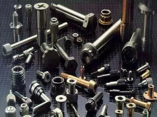
Hex head bolt dimensions • There are four primary dimensions of a hex head bolt: • [A] Thread diameter • [B] Thread length • [C] Thread pitch • [D] Hex size [distance between flats]
Distance between flats • The hex size determines the size of the wrench needed to loosen and tighten the bolt • The hex size is not standardized • A bolt with a diameter of 8mm and a thread pitch of 1.25mm will have a hex size of 12mm on an Asian car • An 8mm bolt with a 1.25mm pitch will have a hex size of 13mm on a European car 8 x 1.25mm 12mm Asian 8 x 1.25mm 13mm European
Thread pitch • In the metric system the thread pitch is the distance in millimeters between each thread • Threads that are spacedd close together are called ‘fine’ whereas threads that are spaced far apart all called ‘coarse’ 1.5mm Coarse 1.25mm Fine
Metric standard and fine thread pitch Bolt Dia. Standard Fine Super Fine 6mm 1.0 7mm 1.0 8mm 1.25 1.0 10mm 1.5 1.25 1.0 12mm 1.75 1.5 1.25 14mm 2.0 1.5 16mm 2.0 18mm 2.5 20mm 2.5
US standard coarse and fine thread pitch Bolt Dia. UNC Coarse UNF Fine 1/4” 20 28 5/16” 18 24 3/8” 16 24 7/16” 14 20 1/2” 13 20 9/16” 12 18 5/8” 11 18 3/4” 10 16
USS and SAE • In the US system coarse thread bolts may be called UNC or USS bolts [Unified National Coarse or United States Standard] • Fine thread bolts may be called UNF or SAE [Unified National Fine or Society of Automotive Engineers]
Coarse thread vs. fine thread • Fine thread bolts have superior holding ability but they can only be used with hard metals [steel] • Soft metals such as aluminum, cast iron and brass will not tolerate the stress that can be applied to a fine thread bolt
Determining thread diameter • Thread diameter is measured in the threaded end of the bolt between the high points of the threads [peak to peak] • The shank [unthreaded section is normally slightly smaller than the threaded section Shank
Determining bolt length • Bolt length is the distance between the bottom of the bolt head and the end of the threads • Universal replacement bolts sold in auto supply stores normally come in 5mm increments 40mm
Determining thread pitch • Thread pitch is measured with a thread pitch gauge • If all of the teeth fall into the thread valleys the thread pitch is equal to the number stamped on the blade • Place the teeth of one of the gage blades lengthwise along the threads of the bolt
Internal thread pitch • The thread pitch gauge can also measure internal threads • It is not easy to see the gauge teeth when measuring internal threads • Identifying the correct pitch on an internal thread is done more by feel than by eye
Bolt dimensions • When ordering metric add the letter ‘M’ in front of the dimensions • The order of dimensions is: • Diameter • Pitch • Length M8 x 1.25 - 40 • The bolt listed here: • Is 8mm in diameter • Has a 1.25mm thread pitch • Is 40mm long
US standard bolts • US Standard bolts may have a UNC or UNF prefix [Unified National Coarse or Unified National Fine] • The bolt dimensions are in the same order [diameter, pitch and length] 1/4 x 20 - 3/4 • Thread pitch is expressed in threads per inch in US Standard bolt nomenclature
Bolt gauge • Bolt distributers often give away plastic bolt gauges that make it easier to identify bolt diameter and length
Grade number • The bolts used to hold automotive parts together must be stronger than general purpose bolts used for household applications • Bolts are graded by the tensile strength of the steel the bold is made from • Tensile strength is the maximum amount of force [pull] that can be applied to a bolt before the bolt will not return to its original length after the pressure is released • The yield strength is the amount of force [pull] it takes to make the bolt break
US standard bolt grade numbers • Grade 3 – approx 100,000 psi / sq in • Should not be used for automotive applications • Grade 5 – 120,000 psi /sq in • OK for low stress automotive uses – accessory brackets, exhaust system etc. • Grade 8 – 150,00 psi / sq in • Needed for high stress components – rod bolts, clutch and flywheel bolts etc.
Metric bolt grade numbers • Metric bolts have a number stamped on the head of the bolt that indicates both tensile and yield strength 10.9 • The number in front of the decimal point is 1/10th of the tensile strength measured in kg/mm2 • In the example here the bolt is made from steel that can withstand 100 kilograms of force over one square millimeter and still return to its original length • The number after the decimal point is the 1/10th of the percentage of tensile strength to the yield strength • In the example the tensile strength is 90% of the yield strength
Metric grade numbers • Unmarked - equivalent of Grade 3 • Should not be used for automotive applications • 8.8 Equivalent to Grade 5 • OK for low stress automotive uses – accessory brackets, exhaust system etc. • 10.9 Equivalent to Grade 8 • Needed for high stress components – rod bolts, clutch and flywheel bolts etc.
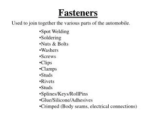
Flat washers • A flat washer is placed between the head of the bolt and the component for a number of reasons: • Never use more than one flat washer per bolt • Besides the fact that the retaining bolt will loosen over time the use of multiple washers is evidence of shoddy workmanship • The flat washer distributes the clamping load over a greater surface area • The use of flat washers helps to achieve a more accurate torque value • The flat washer prevents gouging on soft metal or painted/plated surfaces
Lock washers • Split lock washers are made of spring steel and have a sharp edge that bites into the base metal to prevent the bolt from loosening • Split lock washers are not very effective and are not normally found on modern cars • Star washers have sharp radial spurs that dig into the base metal to prevent loosening • Star washers are often used on chassis ground electrical terminals • Wave washers and Belleville washers are made of thin spring steel and provide a small amount of spring tension to the clamping load Split Star Wave
Flange bolts • Most modern automotive threaded fasteners usually have the flat washer integrated into the head of the bolt or nut. • Often the lower surface of the integrated washer is serrated to help prevent the nut or bolt from loosening • The integrated washer allows the hex to be smaller – which allows the bolt to fit into tight places making installation easier • This type of bolt is called a ‘Flange Bolt’ Serrated lower surface
Nylock nuts • Nylock nuts are often used in applications where minimal clamping force is needed – valve covers etc. • Nylock nuts have a nylon ring embedded in a groove at the top of the nut that prevents the nut loosening Nylon ring • Nylock nuts cannot be used in high temperature applications
All metal lock nuts • This type of nut is similar in appearance to a nylock nut but can withstand high temperatures • Instead of nylon the top thread is pinched inward at four points and is slightly out of round Top thread is out of round
Allen and Torx head bolts • Allen head and Torx head bolts have recessed caps that require an Allen or Torx sockets • Torx head bolts have become popular in recent years because they provide the maximum amount of surface area exposed to torquing force of any common fastener so they are less likely to be deformed during torquing and de-torquing • The Torx head bolt allows for more accurate torquing of machine assembled components Allen head Torx head
Torx head screws and bolts • Torx head screws are commonly used in the assembly of small lightweight chassis components • Headlight assemblies • Instrument clusters • Heating and air conditioning under-dash components etc. • The size of a female Torx screw is expressed as a number after the letter ‘T’ • Torx screws normally range from T8 to T65
External Torx bolt heads • External [male] Torx head screws are commonly found in modern automotive engines • External Torx head bolts will require special sockets that have the letter ‘E’ preceding the size number • External Torx head screws and bolts normally range from E4 to E24 • The numbers for external Torx bolts are much smaller than internal • A T55 bolt has the same internal dimensions as the external dimensions of an E12 bolt
Machine screws • Machine screws are small screws used in subassemblies such as instrument clusters, heater controls etc. • US Standard machine screws are numbered • When as hash mark ‘#’ is placed in front of a number it denotes a US Standard machine screw • Metric machine screws are preceded by the letter M and do not use the hash mark ‘#’ so the size designation is the same as regular metric bolts • Unlike conventional bolts, machine screws are normally threaded their full length
US Standard machine screws num pitch dia. #4 40 0.112” #6 32 0.138” #8 32 0.164 #10 24 & 32 0.190 #12 24 0.216
Metric machine screws num pitch dia. M1 .25 1.0 mm M1.22 .25 1.2mm M1.4 .30 1.4mm M1.6 0.35 1.6mm M2 0.40 2.0mm M2.5 0.45 2.5mm M3 0.50 3.0mm M3.5 0.60 3.5mm M4 0.70 4.0mm M5 0.80 5.0mm
Thread engagement • Bolts that are threaded into engine blocks, cylinder heads, etc. must be long enough to insure the threads on the bolt have sufficient grip to withstand the stress when the bolt is torqued to specifications.
Bolt to Short • If the bolt is too short the threads in the block or the bolt will be stripped • If the threads in the block are stripped the hole will need to be drilled oversize and a thread insert [Heli-Coil] installed
Bolt to Long • If the bolt is too long it will bottom out and bind in the hold. • Do not install extra washers to correct this –additional washers will reduce the clamping force • If the bolt snaps when its torqued you will not be able to remove the broken stub with an EZ-out because the threads are bound
Thread engagement – Dia./Length ratio • Lightly stressed bolts that thread into cast iron or steel housings should have a minimum threat engagement ratio of 1 to 1 • A 1.5 ratio is better • Aluminum, brass and other soft metals require more thread engagement – typically 2 to 3 times the bolt diameter 8 mm 8 mm
Thread engagement – visual check 8 mm • When installing a bolt check how far the head of the bolt is from the component when the threads first catch. • The head of the bolt should extend 1 to 1.5 times its diameter on lightly stressed bolts • Heavily stressed bolts [head bolts, main bearing cap bolts etc.] will have threads engaged 3 to 4 times their diameter 8 mm
Shoulder bolts • Shoulder bolts have a shank that is much wider than the threads • They allow for a fixed gap between the housing/flange surface and the head of the bolt • Shoulder bolts are found on flexible exhaust flanges and valve covers where soft silicone gaskets are used • The shoulder bolt prevents the soft rubber gasket from being damaged by over tightening the bolts
Left hand threaded fasteners • Nearly all threaded fasteners use right hand threads • A right hand threaded bolt is tightened when rotated clockwise – to the right as viewed at the top • Left hand thread fasteners a threaded in the opposite direction • A left hand threaded bolt is tightened when turned counter-clockwise – to the left as viewed at the top • Left handed fasteners are often stamped with the letter ‘L’
Applications for left hand threads • The most common application for left handed threads are the tie rod ends in the steering linkage Sleeve Right hand threads Left hand threads • The outboard tie rod shaft has right hand threads and a right hand locknut • The inboard tie rod shaft has left hand threads and a left hand lock nut • The center sleeve has left hand threads on the inboard end and right hand threads on the outboard end. • When the sleeve is rotated in one direction – the tie rod gets longer. Rotate the sleeve in the opposite direction and the tie rod gets shorter
Studs • Intake and exhaust are often retained by studs and nuts instead of bolts • Studs are often used on aluminum heads and blocks. • They eliminate the potential for damage to the soft threads in the aluminum castings when components are removed and installed
Studs • An unthreaded ‘shoulder’ separates the two threaded ends of the stud • The shoulder is slightly larger than the threaded sections. This allows the stud to be retained tightly to the casting • Most studs for modern engines have a external [male] Torx end that simplifies installation Torx head Shoulder
Hand Wrenches • Adjustable • Open end • Box end • Combination • Flare nut • Ratcheting
Adjustable wrench Only two stress point • Adjustable wrenches should never be used to loosen or tighten automotive fasteners • They often found in an emergency tool kit but you’d be better off with an inexpensive set of sockets • There are many different types, but all of them will damaged the head of the bolt if a large amount of torque is applied
Open end wrench • Only useful in places where a socket or box end wrench can’t reach – exhaust manifold bolts, valve lash adjuster lock nuts etc. • The wrench size of each end of a double open end wrench is a different– 6 wrenches can cover 12 sizes