Download
1 / 26
260 likes | 457 Vues
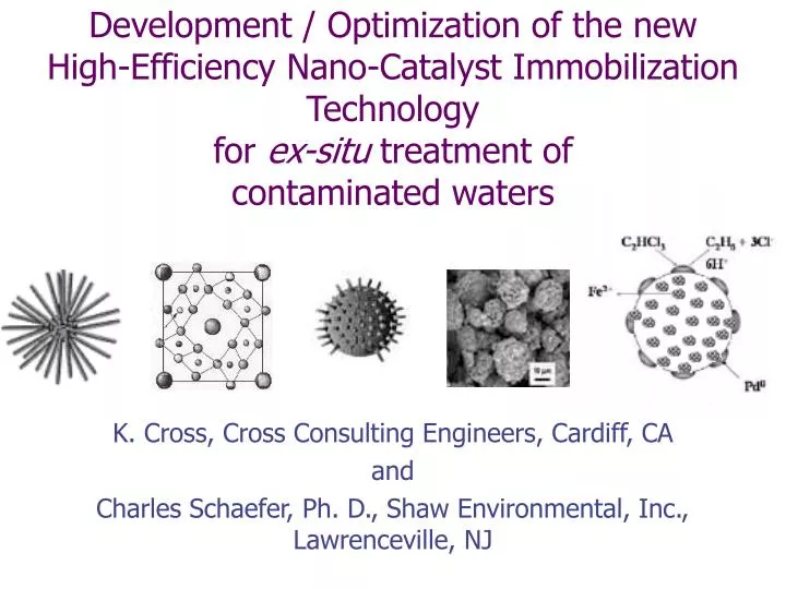
Development / Optimization of the new High-Efficiency Nano-Catalyst Immobilization Technology for ex-situ treatment of contaminated waters. K. Cross, Cross Consulting Engineers, Cardiff, CA and Charles Schaefer, Ph. D., Shaw Environmental, Inc., Lawrenceville, NJ .

E N D
Development / Optimization of the new High-Efficiency Nano-Catalyst Immobilization Technology for ex-situ treatment of contaminated waters K. Cross, Cross Consulting Engineers, Cardiff, CA and Charles Schaefer, Ph. D., Shaw Environmental, Inc., Lawrenceville, NJ
Overall Introduction and Outline • Section 1: Overview of treatment w micro/nano-particles • Section 2: HENCI Technology Overview • HENCI TOP • Phase 1 tests of late ’04 • Section 3: Phase 2 Testing • Objectives and key issues • Scope of Experiments • HENCI Reactor sub-optimization and sizing • Section 4: Phase 3 Pilot Test • Objectives • Approach • Potential Sites • HENCI System Process PID’s • Cost Evaluations
Section 1 Micro / Nano-Catalyzed Remediation Overview
NanoTech now has ~2000 Application Categories - all sectors http://azonano.com/Applications.asp CNST / CBEN at Rice University:“We developed high-performance nano-scale catalysts for treating particularly challenging contaminants in water that must be removed to a very low level.” In-Situ Success with Pd/Fe on TCE by Zhang, Schrick, et. al. Rapid, Complete, Inexpensive Breakdown of ~50 (so far) ubiquitous recalcitrant carcinogenics at sub-ppb levels Cl’d Olefinics, Cl’d Aromatics, THMs, Pesticides, PCHs, PCBs, Dyes, NDMA, TNT, Cr2O2,AsO3, NO, Hg, Ni, City Redlands, CA Env. Council:“TCE and PCPs contamin-ating about half the wells in Midwest and Western U.S. Many in Redlands have been closed due to the high levels of TCE” Micro/Nano-Catalysis Highlights
Ex Situ Treatment of Waters Containing Organic Contaminants • Groundwater • Drinking water • Leachate • Wash Down Bio-reactors Thermal CATOX UV-oxidation Activated Carbon
Zero Valent Metal Particles for Treatment of Organic Contaminants
Zero Valent Metal Particles • Zero Valent metals have been show to treat a wide range of compounds: • Chlorinated solvents • Explosives (e.g., TNT, RDX) • NDMA • Nitrate • Perchlorate (?) • Limited use in ex situ treatment systems due to: • Longevity • Matrix Effects • Particle Retention
Conceptual Model H+ RX Un-catalyzed ZVI RH + X- + Fe2+ Fe H+ H2O RX RH + X- Catalyst e- H+ Catalyzed ZVI Fe2+ + H2 Fe
Reactor Data • 3 hour residence time • 10g Ni catalyst • TCE converted to ethane • No sulfate reduction • No nickel in effluent • Influent DO = 8 mg/L Influent = artificial groundwater containing TCE, sulfate, nitrate, carbonate, and manganese
Reactor Data • 3 hour residence time • 10g Ni catalyst • No sulfate reduction • Influent DO = 8 mg/L • Nitrate reduction Influent = artificial groundwater containing sulfate, nitrate, carbonate, and manganese
Reactor Data Influent TCE 1 ppm Catalyst regeneration using dilute acid Influent = artificial groundwater containing sulfate, nitrate, carbonate, and manganese
pH7.2 Ni NZVI Geochemical Effects on observed PCE Degradation Rate Constants
Batch Data - Mixtures NZVI Treatment • Timescale of weeks • NDMA inhibits PCE decay • 1st-order decay • Negligible sorption
Section 2 HENCI Overview
HENCIHigh-Efficiency Nano-Catalyst Immobilization • As Previously noted, due to their size (and also structure / morphology), micro/nano-particles rapidly degrade many dissolved contaminants • However, due to their small size, there has been no way to cost-effectively immobilize large quantities of MNPs in a flow-through reactor • HENCI cost-effectively immobilizes most nano- & micro-catalysts in a new and novel way, free of the main technical and financial drawbacks inherent to today’s less viable technologies: • Homogeneous, Dense Dispersion – no channeling • Insignificant Del-P even at high flows = Low Cost • Often NO NEW CONTACT MATERIALSexposed to stream
What HENCI Means to the Process Engineer • All advantages of a Continuous Packed-Bed Reactor • No moving parts • Nanoparticle agglomeration can be tuned out • HENCI can immobilize any new macro-structured nanocatalysts which have high-µ or paramagnetic components • Multiple Standardized HENCI units can be Manifolded • Valved in series, parallel or any combination ‘on-line’ • Process any combination of Inlet stream flow rate and concentration
Phase 1 Results (late 2004) • Prototype Rxrs Immobilized ¼ g of BNPC’s per cm3 @ ~2gpm • Video Clip shows release of particles upon unit power-down • Greater loading capacities very likely achievable • HENCI Immobilization force more than adequate for all app’s • Negligible Pressure Drops: allows High Flows, Long Reactors • HENCI Prototypes operated with TCE - polluted inlet stream • Preliminary Trial Report Circulated to NWRI Early ’05 • TCE Run data yield fast Pseudo First-Order Rate Constants • No effect on efficacy of catalyst by HENCI observed • Verification of results is one task of phase 2
Section 3: Phase II Development Locations: Shaw Environmental, Inc. Lawrenceville, NJ Cross Consulting Cardiff, CA • 1: NMCR Database • Gather data from Treatability Studies and literature • Compile into ever-growing NMCR Database • 2: Treatability Studies / RXR Development • Build several bench-scale rxrs, install in Shaw’s Lab • verify degradation of target contaminants in site groundwater • determine the most appropriate metallic particles • determine degradation kinetics reactor residence time • estimate extent of particle “change-out” or regeneration • Use data and experience to incorporate improvements to reactors Objectives
Phase II Testing • site groundwater • degradation end products • kinetics 1. Batch Screening Tests 2. Bench scale Reactor Testing • reactant loading in HENCI reactor • degradation rates • daughter product generation • reaction longevity • hydraulic properties 3. Data Evaluation & Conceptual Design • calculate rate constants • reactor sizing and optimization
1st-order degradation rate constant to Reactor Sizing and Optimization Key parameter: area = m2/L of catalyst in reactor for ZVI/Pd, area≥ 7130 m2/L k´= k • area Basic Design Equation For 99.9% conversion, = 12 minutes For 1 gpm flow, Reactor volume = 12 Gal Process Optimization Parameters • dEff / dPD goes thru max for each material • Scale-Up Using Optimal RXR tres • Reactor / system configuration det’d from Tresmin and Inlet stream flowrate • Total DelP then allows pump sizing, system design, add controls RXR Eff = (% Conversion/ (Tresx MassBNMC) ) Fluid Dyn. Eff = SABET / (PSID / GPM / Axs) = SABET / (PSID / v)
Section 4: Phase III - Pilot Demonstration Objectives • Demonstrate HENCI particle retention system at the field scale • Remediate in-field: Verify treatment effectiveness of target contaminants • Evaluate long-term operation • Identify potential design improvements and modifications
Potential Sites Picatinny Arsenal, Dover, NJ • Existing P&T system operated by Shaw • TCE1000 µg/L • Low ppb levels CT, DCE, VC Former Naval Surface Warfare Ctr, White Oak, MD • former waste water discharge area • TCE, TNT, RDX 19th St. GAC Plant City of San Bernardino • ~7ppb TCE, ~ 5ppb NDMA
Approach • Construct and install HENCI System with selected nano/micro particles, controls, redundancies • Treat and monitor for 3 to 4 months (1 gpm flow) • Perform O&M activities as needed • Evaluate results with respect to overall treatment effectiveness and costs
Summary • Rapid and cost-effective ex-situ treatment of a variety of contaminants • HENCI technology applicable to wide range of nano/micro particles • Significant Potential to revolutinize CHC Site remediation – Point-of-Distribution Systems: Pump/Treat, and USE! • Reactor-based nanocatalysis will merit applications in other Environmental sub-sectors as Rural P.O.D., portable/Field unit, and other non-Groundwater applications arise • Potential to Usher in new era in water remediation globally