Download
1 / 1
10 likes | 96 Vues
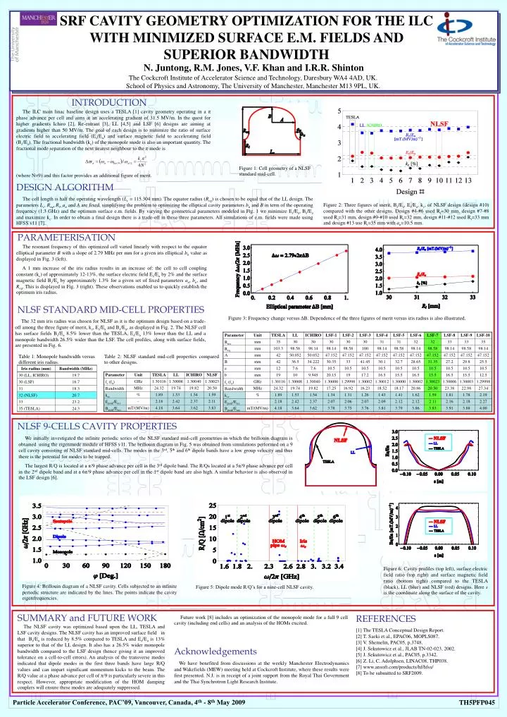
Figure 1: Cell geometry of a NLSF standard mid-cell.

E N D
Figure 1: Cell geometry of a NLSF standard mid-cell. Figure 6: Cavity profiles (top left), surface electric field ratio (top right) and surface magnetic field ratio (bottom right) compared to the TESLA (black), LL (blue) and NLSF (red) designs. Here s is the coordinate along the surface of the cavity. Figure 5: Dipole mode R/Q’s for a nine-cell NLSF cavity. Figure 4: Brillouin diagram of a NLSF cavity. Cells subjected to an infinite periodic structure are indicated by the lines. The points indicate the cavity eigenfrequencies. SRF CAVITY GEOMETRY OPTIMIZATION FOR THE ILC WITH MINIMIZED SURFACE E.M. FIELDS AND SUPERIOR BANDWIDTH N. Juntong, R.M. Jones, V.F. Khan and I.R.R. Shinton The Cockcroft Institute of Accelerator Science and Technology, Daresbury WA4 4AD, UK.School of Physics and Astronomy, The University of Manchester, Manchester M13 9PL, UK. INTRODUCTION The ILC main linac baseline design uses a TESLA [1] cavity geometry operating in a π phase advance per cell and aims at an accelerating gradient of 31.5 MV/m. In the quest for higher gradients Ichiro [2], Re-entrant [3], LL [4,5] and LSF [6] designs are aiming at gradients higher than 50 MV/m. The goal of each design is to minimize the ratio of surface electric field to accelerating field (Es/Ea) and surface magnetic field to accelerating field (Bs/Ea). The fractional bandwidth (kc) of the monopole mode is also an important quantity. The fractional mode separation of the next nearest neighbour to the π mode is (where N=9) and this factor provides an additional figure of merit. DESIGN ALGORITHM The cell length is half the operating wavelength (Lc = 115.304 mm). The equator radius (Req) is chosen to be equal that of the LL design. The parameters Lc, Req, Ri, an and A are fixed, simplifying the problem to optimizing the elliptical cavity parameters bn and B in term of the operating frequency (1.3 GHz) and the optimum surface e.m. fields. By varying the geometrical parameters modeled in Fig. 1 we minimize Es/Ea, Bs/Ea and maximize kc. In order to obtain a final design there is a trade-off in these three parameters. All simulations of e.m. fields were made using HFSS v11 [7]. Figure 2: Three figures of merit, Bs/Ea,Es/Ea, kc, of NLSF design (design #10) compared with the other designs. Design #4-#6 used Ri=30 mm, design #7-#8 used Ri=31 mm, design #9-#10 used Ri=32 mm, design #11-#12 used Ri=33 mm and design #13 use Ri=35 mm with an=10.5 mm. PARAMETERISATION The resonant frequency of this optimized cell varied linearly with respect to the equator elliptical parameter B with a slope of 2.79 MHz per mm for a given iris elliptical bn value as displayed in Fig. 3 (left). A 1 mm increase of the iris radius results in an increase of: the cell to cell coupling constant (kc) of approximately 12-13%, the surface electric field Es/Ea by 2% and the surface magnetic field Bs/Ea by approximately 1.3% for a given set of fixed parameters an, bn, and Req. This is displayed in Fig. 3 (right). These observations enabled us to quickly establish the optimum iris radius. NLSF STANDARD MID-CELL PROPERTIES Figure 3: Frequency change versus ΔB. Dependence of the three figures of merit versus iris radius is also illustrated. The 32 mm iris radius was chosen for NLSF as it is the optimum design based on a trade-off among the three figure of merit, kc, Es/Ea and Bs/Ea, as displayed in Fig. 2. The NLSF cell has surface fields Bs/Ea 8.5% lower than the TESLA, Es/Ea 13% lower than the LL and a monopole bandwidth 26.5% wider than the LSF. The cell profiles, along with surface fields, are presented in Fig. 6. Table 1: Monopole bandwidth versus different iris radius. Table 2: NLSF standard mid-cell properties compared to other designs. NLSF 9-CELLS CAVITY PROPERTIES We initially investigated the infinite periodic series of the NLSF standard mid-cell geometries in which the brillouin diagram is obtained using the eigenmode module of HFSS v11. The brillouin diagram in Fig. 5 was obtained from simulations performed on a 9 cell cavity consisting of NLSF standard mid-cells. The modes in the 3rd, 5th and 6th dipole bands have a low group velocity and thus there is the potential for modes to be trapped. The largest R/Q is located at a π/9 phase advance per cell in the 3rd dipole band. The R/Qs located at a 5π/9 phase advance per cell in the 2nd dipole band and at a 6π/9 phase advance per cell in the 1st dipole band are also high. A similar behavior is also observed in the LSF design [6]. SUMMARY and FUTURE WORK REFERENCES Future work [8] includes an optimization of the monopole mode for a full 9 cell cavity (including end cells) and an analysis of the HOMs excited. The NLSF cavity was optimized based upon the LL, TESLA and LSF cavity designs. The NLSF cavity has an improved surface field in that Bs/Ea is reduced by 8.5% compared to TESLA and Es/Ea is 13% superior to that of the LL design. It also has a 26.5% wider monopole bandwidth compared to the LSF design (hence giving it an improved tolerance on a cell-to-cell errors). An analysis of the transverse modes indicated that dipole modes in the first three bands have large R/Q values and can impart significant momentum kicks to the beam. The R/Q value at a phase advance per cell of π/9 is particularly severe in this respect. However, appropriate modification of the HOM damping couplers will ensure these modes are adequately suppressed. [1] The TESLA Conceptual Design Report. [2] T. Saeki et al., EPAC06, MOPLS087. [3] V. Shemelin, PAC05, p.3748. [4] J. Sekutowicz et al., JLAB TN-02-023, 2002. [5] J. Sekutowicz et al., PAC05, p.3342. [6] Z. Li, C. Adolphsen, LINAC08, THP038. [7] www.ansoft.com/products/hf/hfss/ [8] To be submitted to SRF2009. Acknowledgements We have benefited from discussions at the weekly Manchester Electrodynamics and Wakefields (MEW) meeting held at Cockcroft Institute, where these results were first presented. N.J. is in receipt of a joint support from the Royal Thai Government and the Thai Synchrotron Light Research Institute. Particle Accelerator Conference, PAC’09, Vancouver, Canada, 4th - 8th May 2009 TH5PFP045