Download
1 / 111
1.27k likes | 1.92k Vues
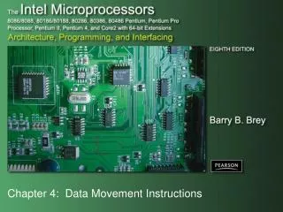
Chapter 4: Data Movement Instructions. Introduction. This chapter concentrates on the data movement instructions. The data movement instructions include MOV, MOVSX, MOVZX, PUSH, POP, BSWAP, XCHG, XLAT, IN, OUT, LEA, LDS, LES, LFS, LGS, LSS, LAHF, SAHF.

E N D
Introduction • This chapter concentrates on the data movement instructions. • The data movement instructions include MOV, MOVSX, MOVZX, PUSH, POP, BSWAP, XCHG, XLAT, IN, OUT, LEA, LDS, LES, LFS, LGS, LSS, LAHF, SAHF. • String instructions: MOVS, LODS, STOS, INS, and OUTS.
Chapter Objectives Upon completion of this chapter, you will be able to: • Explain the operation of each data movement instruction with applicable addressing modes. • Explain the purposes of the assembly language pseudo-operations and key words such as ALIGN, ASSUME, DB, DD, DW, END, ENDS, ENDP, EQU, .MODEL, OFFSET, ORG, PROC, PTR, SEGMENT, USEI6, USE32, and USES.
Chapter Objectives (cont.) Upon completion of this chapter, you will be able to: • Select the appropriate assembly language instruction to accomplish a specific data movement task. • Determine the symbolic opcode, source, destination, and addressing mode for a hexadecimal machine language instruction. • Use the assembler to set up a data segment, stack segment, and code segment.
Chapter Objectives (cont.) Upon completion of this chapter, you will be able to: • Show how to set up a procedure using PROC and ENDP. • Explain the difference between memory models and full-segment definitions for the MASM assembler. • Use the Visual online assembler to perform data movement tasks.
4–1 MOV Revisited • In this chapter, the MOV instruction introduces machine language instructions available with various addressing modes and instructions. • It may be necessary to interpret machine language programs generated by an assembler. • Occasionally, machine language patches are made by using the DEBUG program availablewith DOS and Visual for Windows.
Machine Language • Native binary code microprocessor uses as its instructions to control its operation. • instructions vary in length from 1 to 13 bytes • Over 100,000 variations of machine language instructions. • there is no complete list of these variations • Some bits in a machine language instruction are given; remaining bits are determined for each variation of the instruction.
Figure 4–1 The formats of the 8086–Core2 instructions. (a) The 16-bit form and (b) the 32-bit form. • 80386 and above assume all instructions are 16-bit mode instructions when the machine is operated in the real mode (DOS). • in protected mode (Windows), the upper byte of the descriptor contains the D-bit that selects either the 16- or 32-bit instruction mode
The Opcode • Selects the operation (addition, subtraction, etc.,) performed by the microprocessor. • either 1 or 2 bytes long for most instructions • Figure 4–2 illustrates the general form of the first opcode byte of many instructions. • first 6 bits of the first byte are the binary opcode • remaining 2 bits indicate the direction (D) of the data flow, and indicate whether the data are abyte or a word (W)
Figure 4–2 Byte 1 of many machine language instructions, showing the position of the D- and W-bits.
Figure 4–3 Byte 2 of many machine language instructions, showing the position of the MOD, REG, and R/M fields.
MOD Field • Specifies addressing mode (MOD) and whether a displacement is present with the selected type. • If MOD field contains an 11, it selects the register-addressing mode • Register addressing specifies a register insteadof a memory location, using the R/M field • If the MOD field contains a 00, 01, or 10, the R/M field selects one of the data memory-addressing modes.
All 8-bit displacements are sign-extended into 16-bit displacements when the processor executes the instruction. • if the 8-bit displacement is 00H–7FH (positive),it is sign-extended to 0000H–007FH before adding to the offset address • if the 8-bit displacement is 80H–FFH (negative),it is sign-extended to FF80H–FFFFH • Some assembler programs do not use the 8-bit displacements and in place default to all 16-bit displacements.
Register Assignments • Suppose a 2-byte instruction, 8BECH, appears in a machine language program. • neither a 67H (operand address-size override prefix) nor a 66H (register-size override prefix) appears as the first byte, thus the first byte is the opcode • In 16-bit mode, this instruction is converted to binary and placed in the instruction format of bytes 1 and 2, as illustrated in Figure 4–4.
Figure 4–4 The 8BEC instruction placed into bytes 1 and 2 formats from Figures 4–2 and 4–3. This instruction is a MOV BP,SP. • the opcode is 100010, a MOV instruction • D and W bits are a logic 1, so a word moves into the destination register specified in the REG field • REG field contains 101, indicating register BP, so the MOV instruction moves data into register BP
R/M Memory Addressing • If the MOD field contains a 00, 01, or 10, the R/M field takes on a new meaning. • Figure 4–5 illustrates the machine language version of the 16-bit instruction MOV DL,[DI] or instruction (8AI5H). • This instruction is 2 bytes long and has an opcode 100010, D=1 (to REG from R/M), W=0 (byte), MOD=00 (no displacement), REG=010 (DL), and R/M=101 ([DI]).
Figure 4–5 A MOV DL,[DI] instruction converted to its machine language form. • If the instruction changes to MOV DL, [DI+1], the MOD field changes to 01 for 8-bit displacement • first 2 bytes of the instruction remain the same • instruction now becomes 8A5501H instead of 8A15H
Because the MOD field contains a 11, the R/M field also indicates a register. • R/M = 100(SP); therefore, this instruction moves data from SP into BP. • written in symbolic form as a MOV BP,SP instruction • The assembler program keeps track of the register- and address-size prefixes and the mode of operation.
Special Addressing Mode • A special addressing mode occurs when memory data are referenced by only the displacement mode of addressing for 16-bit instructions. • Examples are the MOV [1000H],DL and MOV NUMB,DL instructions. • first instruction moves contents of register DL into data segment memory location 1000H • second moves register DL into symbolic data segment memory location NUMB
When an instruction has only a displacement, MOD field is always 00; R/M field always 110. • You cannot actually use addressing mode [BP] without a displacement in machine language • If the individual translating this symbolic instruction into machine language does not know about the special addressing mode, the instruction would incorrectly translate to a MOV [BP],DL instruction.
Figure 4–6 The MOV [1000H],DI instruction uses the special addressing mode. • bit pattern required to encode the MOV [1000H],DL instructionin machine language
Figure 4–7 The MOV [BP],DL instruction converted to binary machine language. • actual form of the MOV [BP],DL instruction • a 3-byte instruction witha displacement of 00H
32-Bit Addressing Modes • Found in 80386 and above. • by running in 32-bit instruction mode or • In 16-bit mode by using address-size prefix 67H • A scaled-index byte indicates additional forms of scaled-index addressing. • mainly used when two registers are added to specify the memory address in an instruction • A scaled-index instruction has 215 (32K) possible combinations.
Over 32,000 variations of the MOV instruction alone in the 80386 - Core2 microprocessors. • Figure 4–8 shows the format of the scaled-index byte as selected by a value of 100 in the R/M field of an instruction when the 80386 and above use a 32-bit address. • The leftmost 2 bits select a scaling factor (multiplier) of 1x, 2x, 4x, 8x. • Scaled-index addressing can also use a single register multiplied by a scaling factor.
Figure 4–8 The scaled-index byte. • the index and base fields both contain register numbers
An Immediate Instruction • An example of a 16-bit instruction using immediate addressing. • MOV WORD PTR [BX+1000H] ,1234H moves a 1234H into a word-sized memory location addressed by sum of 1000H, BX, and DS x 10H • 6-byte instruction • 2 bytes for the opcode; 2 bytes are the data of 1234H; 2 bytes are the displacement of 1000H • Figure 4–9 shows the binary bit pattern for each byte of this instruction.
Figure 4–9 A MOV WORD PTR, [BX=1000H] 1234H instruction converted to binary machine language.
This instruction, in symbolic form, includes WORD PTR. • directive indicates to the assembler that the instruction uses a word-sized memory pointer • If the instruction moves a byte of immediate data, BYTE PTR replaces WORD PTR. • if a doubleword of immediate data, the DWORD PTR directive replaces BYTE PTR • Instructions referring to memory through a pointer do not need the BYTE PTR, WORD PTR, or DWORD PTR directives.
Segment MOV Instructions • If contents of a segment register are moved by MOV, PUSH, or POP instructions, a special bits (REG field) select the segment register. • the opcode for this type of MOV instruction is different for the prior MOV instructions • an immediate segment register MOV is not available in the instruction set • To load a segment register with immediate data, first load another register with the data and move it to a segment register.
Figure 4–10 A MOV BX,CS instruction converted to binary machine language. • Figure 4–10 shows a MOV BX,CS instruction converted to binary. • Segment registers can be moved between any 16-bit register or 16-bit memory location.
A program written in symbolic assembly language (assembly language) is rarely assembled by hand into binary machine language. • An assembler program converts symbolic assembly language into machine language.
The 64-Bit Mode for the Pentium 4 and Core2 • In 64-bit mode, a prefix called REX (register extension) is added. • encoded as a 40H–4FH, follows other prefixes; placed immediately before the opcode • Purpose is to modify reg and r/m fields in the second byte of the instruction. • REX is needed to be able to address registers R8 through R15
Figure 4–11 illustrates the structure and application of REX to the second byte of the opcode. • The reg field can only contain register assignments as in other modes of operation • The r/m field contains either a register or memory assignment. • Figure 4–12 shows the scaled-index byte with the REX prefix for more complex addressing modes and also for using a scaling factor in the 64-bit mode of operation.
Figure 4–12 The scaled-index byte and REX prefix for 64-bit operations.
4–2 PUSH/POP • Important instructions that store and retrieve data from the LIFO (last-in, first-out) stack memory. • Six forms of the PUSH and POP instructions: • register, memory, immediate • segment register, flags, all registers • The PUSH and POP immediate & PUSHA and POPA (all registers) available 80286 - Core2.
Register addressing allows contents of any 16-bit register to transfer to & from the stack. • Memory-addressing PUSH and POP instructions store contents of a 16- or 32 bit memory location on the stack or stack data into a memory location. • Immediate addressing allows immediate data to be pushed onto the stack, but not popped off the stack.
Segment register addressing allows contents of any segment register to be pushed onto the stack or removed from the stack. • ES may be pushed, but data from the stack may never be popped into ES • The flags may be pushed or popped fromthat stack. • contents of all registers may be pushed or popped
PUSH • Always transfers 2 bytes of data to the stack; • 80386 and above transfer 2 or 4 bytes • PUSHA instruction copies contents of the internal register set, except the segment registers, to the stack. • PUSHA (push all) instruction copies the registers to the stack in the following order: AX, CX, DX, BX, SP, BP, SI, and DI.
PUSHF (push flags) instruction copies the contents of the flag register to the stack. • PUSHAD and POPAD instructions push and pop the contents of the 32-bit register set in 80386 - Pentium 4. • PUSHA and POPA instructions do not function in the 64-bit mode of operation for the Pentium 4
Figure 4–13 The effect of the PUSH AX instruction on ESP and stack memory locations 37FFH and 37FEH. This instruction is shown at the point after execution.
PUSHA instruction pushes all the internal 16-bit registers onto the stack, illustrated in 4–14. • requires 16 bytes of stack memory space tostore all eight 16-bit registers • After all registers are pushed, the contents of the SP register are decremented by 16. • PUSHA is very useful when the entire register set of 80286 and above must be saved. • PUSHAD instruction places 32-bit register set on the stack in 80386 - Core2. • PUSHAD requires 32 bytes of stack storage
Figure 4–14 The operation of the PUSHA instruction, showing the location and order of stack data.
POP • Performs the inverse operation of PUSH. • POP removes data from the stack and places it in a target 16-bit register, segment register, or a 16-bit memory location. • not available as an immediate POP • POPF (pop flags) removes a 16-bit number from the stack and places it in the flag register; • POPFD removes a 32-bit number from the stack and places it into the extended flag register
POPA (pop all) removes 16 bytes of data from the stack and places them into the following registers, in the order shown: DI, SI, BP, SP, BX, DX, CX, and AX. • reverse order from placement on the stack by PUSHA instruction, causing the same data to return to the same registers • Figure 4–15 shows how the POP BX instruction removes data from the stack and places them into register BX.
Figure 4–15 The POP BX instruction, showing how data are removed from the stack. This instruction is shown after execution.
Initializing the Stack • When the stack area is initialized, load both the stack segment (SS) register and the stack pointer (SP) register. • Figure 4–16 shows how this value causes data to be pushed onto the top of the stack segment with a PUSH CX instruction. • All segments are cyclic in nature • the top location of a segment is contiguouswith the bottom location of the segment
Figure 4–16 The PUSH CX instruction, showing the cyclical nature of the stack segment. This instruction is shown just before execution, to illustrate that the stack bottom is contiguous to the top.
Assembly language stack segment setup: • first statement identifies start of the segment • last statement identifies end of the stack segment • Assembler and linker programs place correct stack segment address in SS and the length of the segment (top of the stack) into SP. • There is no need to load these registers in your program. • unless you wish to change the initial values for some reason
If the stack is not specified, a warning will appear when the program is linked. • Memory section is located in the program segment prefix (PSP), appended to the beginning of each program file. • If you use more memory for the stack, youwill erase information in the PSP. • information critical to the operation of your program and the computer • Error often causes the program to crash.