Download
1 / 25
270 likes | 702 Vues
Detail Design: Use-Case Design . Background on Use Case Design. Have ‘done’ Architectural Design; You know the major (eleven) precepts of good design. Now, we drop down a level to Detail Design Now: Use Case Design; Subsystem Design, and Class Design.

E N D
Background on Use Case Design • Have ‘done’ Architectural Design; • You know the major (eleven) precepts of good design. • Now, we drop down a level to Detail Design • Now: • Use Case Design; • Subsystem Design, and • Class Design. • All are very different and satisfy different purposes. • After class design, you are ready to code. 24
Objectives: Use-Case Design (1 of 2) • Start of ‘Detail Design’ – right above coding. • Verify consistency in use-case implementation • 1. Verify that all necessary behaviors cited in the use case narratives have been distributed along the participating classes • See use case narratives and interaction diagrams • 2. Verify that all associations between design elements (classes and subsystems in layers and other components) needed for the use case realizations have been defined, • See layer architecture and components therein. 24
Objectives: Use-Case Design (2 of 2) • 3. Verify that all of the attributes needed for the use cases have been defined and found in domain models, glossary, etc.. • See class diagrams • 4. Refine the Use-Case Realizations (boundary, control, entity classes and subsystems interfaces) from Use-Case Analysis into design model elements • 5. Ensure application architectural mechanisms (persistence, security, etc.) are incorporated into the use case realizations. • Use Case Realizations are captured via software class diagrams and interaction diagrams for various scenarios. 24
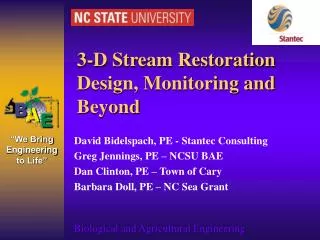
Use-Case Design in Context Architectural Analysis Review the Architecture Describe Architectural Describe Architecture Reviewer Architect Concurrency Design Distribution Subsystem Design Use-Case Analysis Review the Use-Case Design Design Design Designer Reviewer Class Design Here is our workflow suggested by the Unified Process. Note ‘designer’ activities are related to architecture - but quite different from architect Important to note detailed design activities (Use Case, Subsystem, and Class Design) are tightly bound and tend to alternate between one another. 24
Lastly, and very importantly: • Note: one of the major differences between use case analysis (what we have done) and use case design (what we are embarking upon) is scale. • Analysis classes may be quite large • Lots of attributes • This keeps the analysis model small. • Analysis interaction diagrams are quite easy to read and understand and most people will grasp the whole model. • Model is rather small and conceptual! • Model does NOT represent an implementation. (design) 24
Use Case Design - Guidance • Use Case Design Steps: • Describe interactions between design objects • Simplify interaction diagrams using subsystems & interfaces • Will ratchet down in Subsystem Design and Class Design • Let the Use Case ‘drive’ the design process • Ensure interaction diagrams do their job! • Ensure interaction diagrams model the desired behaviors (via requirements) through responsibilities (in design) 24
Supplementary Specifications Design Classes Use Case Use-Case Realization Use-Case Design Overview Design Subsystems and Interfaces Use-Case Design 24
Class Diagrams Sequence Diagrams Use Case Use-Case Realization Use-Case Realization – UML Notation Use-Case Model Design Model Interaction Diagrams: Use Case Realization: Communications Diagrams Use Case Designer is responsible for the integrity of the use case realization. Must coordinate with Architect. 24
Use-Case Design Steps • Describe Interactions Between Design Objects • Involves replacinganalysis classes with designelements. • Replace boundaryclasses (analysis) with subsystems; • Such as GUI classes for boundary classes for a View • Replace externalactors (e.g. external device or a system that manages a database) with an interface to the class; • Will show this ahead… • Note: a number of analysisentities may prevail, although perhaps be fewer in number or adjusted. • In Analysis Interaction Diagrams… • Replace applicable classes (boundary, control, …) with an associated subsystem interface • We are saying that an analysisclass (in the analysismodel) may often be best implemented via a subsystem in the designmodel. (Actually makes our job easier via abstraction) 24
Analysis Classes Design Elements <<boundary>> <<subsystem>> <<subsystem>> BillingSystem CourseCatalogSystem BillingSystem // submit bill() IBillingSystem <<boundary>> CourseCatalogSystem // get course offerings() ICourseCatalogSystem Ex: Incorporating Subsystem Interfaces Using a subsystem as the interface to the Billing System. submitBill(forTuition : Double, forStudent : Student) getCourseOfferings(forSemester : Semester) : CourseOfferingList Note: Interactions to support external system access will be more complex than can be implemented in a single class. So, we identified subsystems to encapsulate this access to external systems. So this type of e boundary class (in analysis) typically morphs into a subsystem in the Design Model. 24
Recall: We had: Our analysis class below: : Course Catalog : Course Catalog System <<boundary>> Actor (hence external) This actor represents the system that manages the Course Catalog, etc. Data is out ‘here.’ Sequence Diagram 24
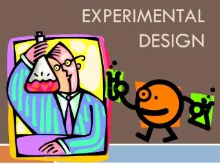
: RegisterForCoursesForm : RegistrationController : CourseCatalogSystem : Schedule : Student : Student 1. // create schedule( ) 1.1. // get course offerings( ) Student wishes to 1.1.1. // get course offerings(forSemester) create a new schedule 1.2. // display course offerings( ) A list of the available course offerings for this semester are displayed 1.3. // display blank schedule( ) A blank schedule is displayed for the students to select offerings 2. // select 4 primary and 2 alternate offerings( ) 2.1. // create schedule with offerings( ) 2.1.1. // create with offerings( ) 2.1.2. // add schedule(Schedule) At this point, the Submit Schedule subflow is executed Ex: Incorporating Subsystem Interfaces(before) Replace with subsystem interface We know from Architectural Design that a CourseCatalogSystem Actor has been defined to represent the external legacy Course Catalog System. So, we need to refine interaction diagram and replace the CourseCatalogSystem boundary class (from analysis) with the associated subsystem interface, ICourseCatalogSystem, here in design. 24
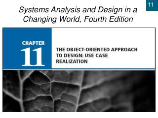
Ex: Incorporating Subsystem Interfaces (after) Now a Design element Replaced with subsystem interface : RegisterForCoursesForm : RegistrationController : ICourseCatalogSystem : Schedule : Student : Student 1: // create schedule( ) 1.1: // get course offerings( ) Student wishes to 1.1.1: getCourseOfferings(Semester) create a new schedule Show here how interactions are modeled between design elements where one element is a subsystem. Original use-case realization from Analysis was refined and original boundary class replaced with the associated subsystem interface, ICourseCatalogSystem Access to the Catalog system is represented via an interface to that subsystem… 1.2: // display course offerings( ) A list of the available course offerings for this semester are displayed 1.3: // display blank schedule( ) A blank schedule is displayed for the students to select offerings 2: // select 4 primary and 2 alternate offerings( ) 2.1: // create schedule with offerings( ) 2.1.1: // create with offerings( ) 2.1.2: // add schedule(Schedule) 24 At this, point the Submit Schedule subflow is executed.
More on interaction diagrams • In Use CaseDesign, we do not flush out the internals of the CourseCatalogSystem subsystem. • How the subsystem accesses the external system that manages the Catalog is abstracted here and represented only by an interface to the subsystem. • The subsystem’s job is to connect to the external system. • This part of the Use Case Design sequence diagram will become the subsystem context diagramin Subsystem Design coming up • When we take on Subsystem Design we will have to design the internals of every subsystem we abstract using only its interface here. 24
Ex: Incorporating Subsystem Interfaces - (VOPC) Subsystem interface <<Interface>> ICourseCatalogSystem <<boundary>> (from External System Interfaces) RegisterForCoursesForm <<control>> 1 (from Registration) 0..* getCourseOfferings() RegistrationController initialize() (from Registration) // submit schedule() // display course offerings() <<entity>> // submit schedule() 1 1 // display schedule() Schedule // save schedule() // save schedule() currentSchedule // create schedule with offerings() (from University Artifacts) 0..1 // create schedule() // getCourseOfferings() semester // select 4 primary and 2 alternate offerings() 0..1 // display blank schedule() 0..1 // submit() // save() registrant 0..1 0..* // any conflicts?() // new() <<entity>> Student. 0..* 0..* (from University Artifacts) - name alternateCourses - address 1 - studentID : int 0..2 primaryCourses <<entity>> 0..4 // addSchedule() CourseOffering // getSchedule() (from University Artifacts) // hasPrerequisites() number // passed() startTime Static part: endTime days The above example is the VOPC after incorporating the design elements. The original CourseCatalogSystem boundary class has been replaced with the associated subsystem interface, ICourseCatalogSystem. // addStudent() // removeStudent() 24 // new() // setData()
Use-Case Design Steps - continued • Simplify Interaction Diagrams Using Subsystems • When a use case is realized (that is, ‘design’), the flow of events is usually described in terms of executing objects; that is, as interactions between design objects. • Often useful to encapsulate a sub-flow of events within a subsystem. (below and next slide) • If done, large subsections of the interaction diagram are replaced with a single message to the subsystem. • This simplifies our first cuts at use-case design and resulting interaction diagrams. • Subsystem interaction diagrams are later developed during Subsystem Design and will illustrate the internal interactions needed to produce each of these desired behaviors. 24
Raises the level of abstraction Encapsulating Subsystem Interactions • Interactions can be described at several levels • Lifelines in the middle represent sub-states; • Interactions in circles represent the internalinteraction of subsystem members in response to the message. • Subsystem interactions can / will be described in their own interaction diagrams 24
Encapsulate Sub-Flows in a Subsystem When a: • Sub-flow occurs in multiple use-case realizations • Sub-flow occurs only in one use case realization, but: • Sub-flow has reuse potential • Sub-flow is complex and easily encapsulated (abstract out the behaviors for now…) • Sub-flow is responsibility of one person/team • Sub-flow produces a well-defined result • Make sure what you are abstracting is worth abstracting. There’s no free lunch! 24
<<subsystem>> MySubsystem :InterfaceA InterfaceA op1() Op1() Guidelines: Encapsulating Subsystem Interactions • Subsystems should be represented ONLY by their interfaces on interaction diagrams in use case design (here) • Messages to subsystems are modeled as messages to the subsystem interface only. • Thus any subsystem that realizes the interface can be substituted for the interface in diagram (later). 24
Guidelines: Messages sent From Interfaces • Messages to subsystems correspond to operations of the subsystem interface (the signatures) • Interactions within subsystems will be modeled in Subsystem Design • Very powerful statements here: Discuss real meanings! • In many cases, the interface lifeline does not have messages going out from it, since different subsystems realizing the interface may send different messages. • However, if you want to describe what messages should be sent (or are allowed to be sent) from any subsystem realizing the interface, such messages can go out from the interface lifeline. 24
Principle: “Design by Contract” • With this approach, when describing the interactions, the focus remains concentrated on the services, NOT on how the services are implemented (realized) within design elements. • This is known as “Design by Contract” and is one of the core tenets of robust software development using abstraction and encapsulation mechanisms. • Describing HOW the services are implemented is the focus of Subsystem Design (for the design subsystems) and Class Design (for the design classes). 24
Advantages of Encapsulating Subsystem Interactions via Interfaces • Use-case realizations are less cluttered – especially if the internal design of subsystem in complex. • Use-case realizations can be created before the internal designs of subsystems are created (parallel development) • Ensures the use case functionality hasn’t been lost between allocation of use-case responsibility (in Use Case Analysis) and the identification of design elements (subsystems and design classes) in Architectural Design, and before Subsystem Design is performed. • Use-case realizations are more generic and easy to change (subsystems can be substituted) • Again, encapsulating subsystem interactions raises the level of abstraction of the use-case realization flows of events. 24
Parallel Subsystem Development • IF we are developing subsystems more or less independently, first find subsystem dependencies by identifying the interfaces between them. How? • Approach: • Concentrate on requirements that affect subsystem interfaces • Outline required interfaces • Show messages that are going to pass over the subsystem borders… • Draw interaction diagrams in terms of subsystem interfaces for each use case • Refine the interfaces needed to provide messages • Develop each subsystem in parallel – using the interfaces as synchronization instruments between development teams. 24
Parallel Subsystem Development • May decide to arrange the interaction diagrams in term of subsystems or in terms of their interfaces only. • In some projects, it might be necessary to implement the classes providing the interfaces before you continue with the rest of the modeling. • The detailed design of the subsystem “internals” is done during Subsystem Design. • Interfaces are what ensure compatibility between the Use-Case Design and Subsystem Design. 24