Download
1 / 30
300 likes | 485 Vues
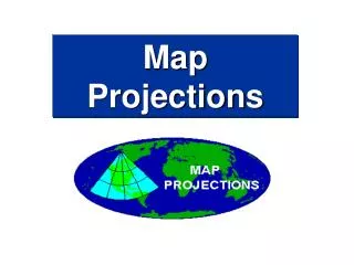
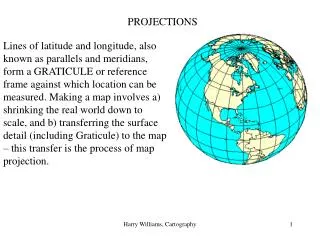
PROJECTIONS. 11.2. DEF: a projection is a representation of a three-dimensional shape on a two-dimensional surface. PROJECTIONS. PROJECTIONS. Projections are arranged into 3 categories: multi-view Isometric oblique. An example of an isometric projection. DRAWING TERMINOLOGY.

E N D
PROJECTIONS 11.2
DEF: a projection is a representation of a three-dimensional shape on a two-dimensional surface. PROJECTIONS
PROJECTIONS Projections are arranged into 3 categories: multi-view Isometric oblique An example of an isometricprojection
DRAWING TERMINOLOGY OBSERVATORY p., 343
PROJECTIONS DIFFER IN 2 ASPECTS: DIFFERENCE #1 DIFFERENCE #2 Angle between the visual rays & the sheet of paper. • Position of the object with respect to the surface it is drawn on. • The table on the next slide will illustrate these differences.
COMMON TYPES OF PROJECTIONS OBSERVATORY p., 344
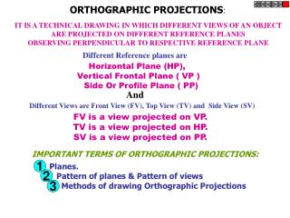
DEF: an orthogonal projection is a projection in which the visual rays are perpendicular from the surface of the paper. ORTHOGONAL PROJECTIONS
ISOMETRIC vs. OBLIQUE ISOMETRIC OBLIQUE
DEF: an isometric projection is a “perspective” drawing of an object where the principal edges are arranged on 3 isometric angles (120o degrees). ISOMETRIC PROJECTIONS
ISOMETRIC PROJECTIONS OBSERVATORY p., 347 OBSERVATORY p., 347
Isometric drawing 50 To create the box, use construction lines to outline an isometric box as large as the overall object to be drawn. We will illustrate the main stages of isometric drawing of the object shown above in multi-view. We will use a method called box construction. The vertical axis is equal to the real height. The two other axes, drawn at 30° to horizontal, correspond to the actual width and length of the object. 20 20 28 35 10 14 8
Isometric drawing Measurements are reported on the isometric axes, or on lines parallel to these axes. The box is an isometric drawing as large as the overall object to be shown. Its lines are drawn very faintly. The object is drawn by removing volumes from the box. A 30º- 60º set square is used to trace the isometric lines.
Isometric drawing Measurements are reported on the isometric axes, or on lines parallel to these axes. The box is an isometric drawing as large as the overall object to be shown. Its lines are drawn very faintly. The object is drawn by removing volumes from the box. A 30º- 60º set square is used to trace the isometric lines.
Isometric drawing STAGE 1 STAGE 2 STAGE 3 STAGES OF DRAWING IN ISOMETRIC PERSPECTIVE Measure on the axesand trace the details in construction lines. Carry out the final layout. Sketch the box.
Isometric drawing STAGES OF DRAWING IN ISOMETRIC PERSPECTIVE STAGE1 STAGE2 STAGE3 Measure on the axes and trace the details in construction lines. Carry out the final layout. Sketch the box.
DEF: a multi-view projection is a 2-D representation of the different views on an object. MULTI-VIEW PROJECTIONS
MULTI-VIEW PROJECTIONS OBSERVATORY P., 345
MULTI-VIEW PROJECTIONS OBSERVATORY P., 346
Try it yourself! • Begin working on the lab entitled projections. • Answer all questions on pages 1-2 and complete the multi-view projection.
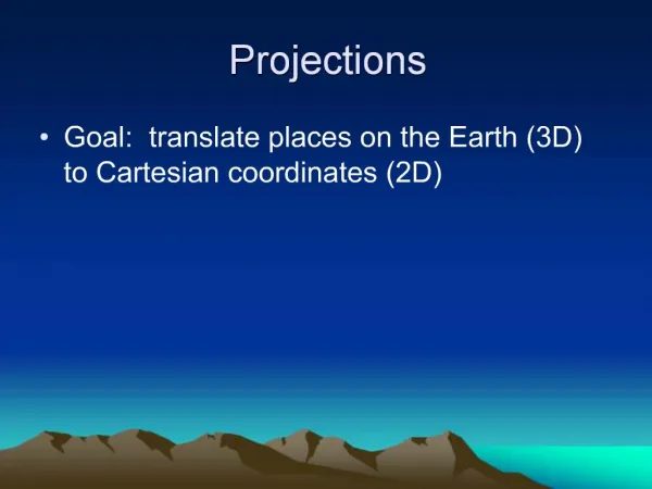
PERSEPCTIVE Drawings with “perspective” represent all 3 dimensions in a single view.
DEF: a perspective drawing in which one of the sides of the object is parallel to the paper, but the depth is represented by parallel lines drawn at oblique angles. OBLIQUE PROJECTIONS
3 main drawings used in an engineering projects are: General Exploded views Detail Drawings THE USE OF PROJECTIONS IN ENGINEERING DRAWINGS
GENERAL DRAWINGS An engineering drawing that shows the overall design of an object. OBSERVATORY p., 349
EXPLODED-VIEW DRAWINGS An engineering drawing that shows the different parts, or features, of the object separately. OBSERVATORY p., 349
DETAIL DRAWINGS An engineering drawing that specifies all of the details necessary to make a particular part of an object.