Download
1 / 26
260 likes | 269 Vues
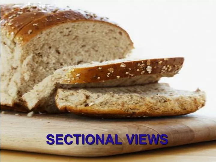
SECTIONAL VIEWS. WHY SECTIONAL VIEWS ?. SECTIONAL VIEWS HELP SIMPLIFY Multiviews can be confusing, especially when there are lots of overlapping hidden lines Sectional Views look inside and only show what we see – There are never hidden lines in a section view

E N D
WHY SECTIONAL VIEWS ? • SECTIONAL VIEWS HELP SIMPLIFY • Multiviews can be confusing, especially when there are lots of overlapping hidden lines • Sectional Views look inside and only show what we see – There are never hidden lines in a section view • You can use section views to dimension to what would be a hidden line in the principle view
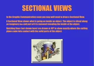
SECTIONAL VIEWS • A sectional view is made by passing an imaginary cutting plane through the part. Then removing and exposing the interior details to view. • The location of imaginary cut is shown in the adjacent view with a cutting-plane line or in a pictorial w/ a short-break line.
Cutting-Plane Line • Darkest, thickest, closest line of all the lines from the Alphabet of Lines • Arrows point to the side of the part we keep • The Section View or a note referring where the section view can be found is immediately behind the arrows • Long dash, two short dashes, long dash
SECTIONAL LINING or a hatch pattern is drawn on any surface that touches the cutting plane
SECTIONAL LINING or cross hatch should be distinctive & is drawn at an angle that is neither parallel or perpendicular to object lines
HIDDEN LINES IN SECTIONING • The purpose of Section Views is to reveal the hidden lines – now that we see those lines, they are no longer hidden and become object lines • If there would or should be more hidden lines behind the cutting plane they are omitted for the sake of clarity.
SECTION LINES IN ASSEMBLY • When there is more then one part assembly should be shown at different angles to show that there multiple parts
SYMBOLS FOR SECTION LINING Sectional lining or cross hatch is a general symbol for material, Hatch patterns are material specific
Can be orthographic & part of the working drawing Or can be pictorial as in an isometric SECTION DRAWINGS
TYPES OF SECTIONS • There are many types of section views, such as • FULL SECTION • HALF SECTION • BROKEN-OUT SECTION • REVOLVED SECTION • REMOVED SECTION • OFFSET SECTION • ALIGNED SECTION
FULL SECTION • A full section is generated by passing a cutting plane fully through an object and removing half of it to give a view of its internal parts
HALF SECTION • A half section is developed by passing the cutting plane halfway through the object, and a quarter of it is removed. The half section is used to show both internal and external features of an object in the same view. It is used primarily for symmetrical objects.
OFFSET SECTION • The path of the cutting plane is not straight. Rather, it conforms (using 90 turns) to the significant features. • Offset section is used to show interior features that can not be located with a single cutting plane
REMOVED SECTION • When there is not enough room on the paper or when it makes better sense - the section view can be placed other then in the adjacent view behind the arrows of the CPL • It is important to clearly label the drawing & reference it behind/or alongside the arrows of the CPL and the page # if on a different page • A removed section can be described as a revolved section that has been removed from the view where it was revolved. It is preferably drawn in line with the axis of cut.
REVOLVED SECTION • Here the cutting plane is passed perpendicular to the object's long axis. The resulting section is then revolved 90° in place to reveal the cut section in true size. A revolved section is used to show the section contour of long object - pipe, beam or handle at desired location.
BROKEN-OUT SECTION A broken-out section is formed by passing a cutting plane through only a small selected portion of the object and using the short break line w/out the CPL
ALIGNED SECTION • Here, some features are rotated to get a conventional revolution view
CONVENTIONAL HOLE REVOLUTIONS (Convention is a standard or acceptable way of doing something)