Download
1 / 13
160 likes | 1.13k Vues
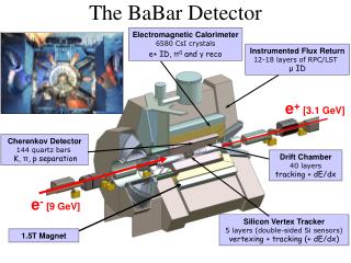
The Product Detector. The product detector’s job is to convert an incoming signal from RF frequencies to audio frequencies. It is simply another mixer whose output is in the audio frequency range. 4 MHz. Product Detector. 4.0008 MHz - 4 MHz = 800 Hz. RF in. Audio out.

E N D
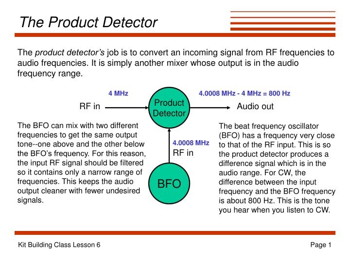
The Product Detector The product detector’s job is to convert an incoming signal from RF frequencies to audio frequencies. It is simply another mixer whose output is in the audio frequency range. 4 MHz Product Detector 4.0008 MHz - 4 MHz = 800 Hz RF in Audio out The BFO can mix with two different frequencies to get the same output tone--one above and the other below the BFO’s frequency. For this reason, the input RF signal should be filtered so it contains only a narrow range of frequencies. This keeps the audio output cleaner with fewer undesired signals. The beat frequency oscillator (BFO) has a frequency very close to that of the RF input. This is so the product detector produces a difference signal which is in the audio range. For CW, the difference between the input frequency and the BFO frequency is about 800 Hz. This is the tone you hear when you listen to CW. 4.0008 MHz RF in BFO Kit Building Class Lesson 6
SW+ Sidetone ~3.9996 MHz 800 Hz 4 MHz Xtal Filter RX Mixer Product Detector BP Filter RF In/Out VFO frequency subtracted here AF Amp BFO ~4.0004 MHz BP Filter Some TX signal “leaks” into RX VFO AF Out ~3 MHz The SW+ sidetone is formed by allowing a bit of the transmitted signal into the receiver. The difference between the transmit LO frequency and the BFO frequency determines the pitch of the sidetone. To zero-beat with another station, simply tune until its pitch matches that of your sidetone. Then you’ll both be on the same frequency. TX Filter, Amp ~3.9996 MHz TX Mixer VFO frequency added here Kit Building Class Lesson 6
SW+ Product Detector Circuit The SW+ product detector circuit uses an NE602 for the mixer just like we’ve seen before. Here, the input comes in from the output of the 4 MHz crystal filter to pin 2. R1 is used to load the output of the filter to match it to the input impedance of the mixer. Since pin 1 isn’t being used it’s tied to ground through a capacitor (C104). Crystal Y4 and capacitors C16, C17, and C18 make up the frequency-determining components for the BFO. C16’s purpose is to pull Y4 up a bit in frequency just like RFC2 pulled the transmit LO down. The output is taken from the mixer in a balanced configuration. The capacitor across pins 4 and 5 is there to allow the RF parts of the mixer output to pass freely, effectively removing it from the AF signal input to the audio amplifier stages. Copyright 1998 Dave Benson NN1G Kit Building Class Lesson 6
Operational Amplifiers V+ • Op amps are IC amplifiers with the • following characteristics: • high input impedance • low output impedance • high gain (up to 100,000) • relatively slow • Op amps accept two inputs, one • which is inverted and the other • not inverted. The op amp then amplifies the difference • between the two signals (it subtracts the inverted input • from the noninverted input and amplifies the result). • In open-loop mode (as shown here), the gain of the op amp is very high, and any difference • between the two inputs causes the amplifier output to saturate. If the inverted input is • larger than the noninverted input, the op amp output is a negative voltage. Otherwise, the • output is positive. Note the two supplies: one is positive, the other is negative. Inverting input - Output + noninverting input V- Kit Building Class Lesson 6
Op Amp Feedback Circuit RF Most of the time we don’t want our amplifier to drive to saturation, so we’d like to reduce its gain to something manageable. We do this by feeding a bit of the output signal back to the inverting input. This has the effect of reducing the difference between the two inputs and reduces the output amplitude. This is called negative feedback. For example, if the inverted input is larger than the noninverted, the output is negative. The feedback to the inverted input serves to reduce its level, lessening the difference between it and the noninverted input. On the other hand, if the inverted input is smaller than the noninverted input, the output is positive, and the feedback serves to increase the level of the inverted input, again lessening the difference between the two inputs. The voltage gain of the op amp in this configuration is simply R1 - + R2 Kit Building Class Lesson 6
Inverting Amplifier RF In the configuration shown here, the inverted input is being compared to ground. This results in the inverted input signal itself being amplified. Since the signal is provided at the inverted input, the output will be inverted with respect to the input. The gain of the amplifier in this configuration is R1 - + Kit Building Class Lesson 6
Noninverting Amplifier RF In the configuration shown here, the noninverted input is being compared to ground. This results in the noninverted input signal itself being amplified. Since the signal is provided at the noninverted input, the output will be in phase with the input. The gain of the amplifier in this configuration is R1 - R2 + Kit Building Class Lesson 6
Source Follower The source follower circuit is a variation on the noninverting amplifier. Here, the feedback resistor has been replaced with a short circuit. This effectively makes the gain of the amplifier to be one. What is the advantage of an amplifer with no gain? Just like the emitter follower amplifier we constructed with a transistor, the source follower has a high input impedance and low output impedance. It will do a good job of isolating one part of the circuit from another. R1 - R2 + Kit Building Class Lesson 6
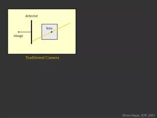
RC Filters In combination with a resistor, a capacitor’s variation in reactance with frequency can be used to construct a simple low-pass or high-pass filter: C Vin Vout Vin R Vout C High-pass filter R Low-pass filter Kit Building Class Lesson 6
Low-Pass Active Filter Passive filters take up lots of space in a circuit and cause signal to be lost. Combining a passive RC filter with an op amp for amplification creates what is known as an active filter. By “active” we mean that the filter requires power to operate. Here is an example of an active low-pass filter. The signal is provided to the noninverted input through an RC low-pass filter made up of R2 and C2. Feedback to limit gain comes through C1 and RF. The parallel combination of C1 and RF presents an impedance which decreases with increasing frequency, meaning that more negative feedback is provided to the inverting input at higher frequencies, reducing gain at those frequencies. C1 RF R1 - R2 + C2 Kit Building Class Lesson 6
High-Pass Active Filter RF R1 - C1 C2 + R2 Here is an example of an active high-pass filter. C2 and R2 make up an RC high-pass filter at the input of the op amp. R3 provides a path for the input when the frequency is too low for C2 to freely conduct. When the input signal passes through R3 instead of into the amplifier, the output is tied directly to the input and the gain is reduced. So, this amplifier has low gain at low frequencies and higher gain at high frequencies. C1 prevent any DC at the input from being coupled to the output. R3 Kit Building Class Lesson 6
SW+ Amplifier First Stage The SW+ first-stage audio amplifier is configured as a low-pass filter. The RC low-pass filter is made up of R4 and C22 (8 volts DC bias is applied to the noninverted input of the op amp through R4). C23 and R7 in the feedback from the output to the inverting input also serve to filter out high frequencies. C19 provides a “short” for high frequency components at the output of the product detector. C20 and C21 are DC blocking capacitors, and R2 and R3 limit current input to the amplifier. Diodes D3 and D4 limit the voltage swing of the output so Q1 (the FET which mutes the receiver during transmit) is not driven to saturation. 12 volts is applied to the V+ input, while the V- is grounded. The 8-volt DC bias on the input serves to put the signal voltage between V+ and V-. Copyright 1998 Dave Benson NN1G Kit Building Class Lesson 6
Install the following parts: Socket for U3, and U3 (SA612) Socket for U4, and U4 (NE5532) C16 through C23 D3 and D4 R2, R3, R4, and R7 Y4 Make sure that the temporary jumper from the base of Q6 (leftmost hole) to the top hole for C36 is still in place (you installed it for lesson 5). Connect power jack, tuning pot, gain pot, and key jack. Connect a key to the key jack, or use a jumper to short the contacts. Turn gain pot all the way up. Connect power. Key down, use oscilloscope to check for a signal at the output (pin 1) of U4. You should see a clear signal of around 800 Hz. Construction Kit Building Class Lesson 6