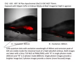
Download
1 / 11
110 likes | 263 Vues
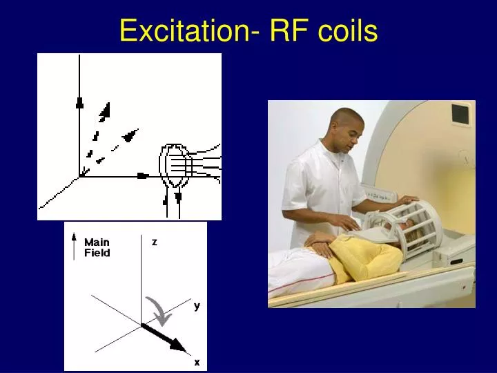
Excitation- RF coils. RF coils. A special coil (antenna) is used to produce the RF field coil is tuned to the appropriate resonant frequency. Surface coil Helmholtz. Coils are made from tuned circuits. RF heating with field strength. More power required to image at high field

E N D
RF coils • A special coil (antenna) is used to produce the RF field • coil is tuned to the appropriate resonant frequency.
RF heating with field strength • More power required to image at high field • RF deposition • Beware of hotspots • Coil modelling
Circular Polarisation • RF magnetic field pointing along x axis and varying sinusoidally is equivalent to 2 circulating polarised fields rotating at ± 1
Effect of a 90 degree pulse Rotating frame Lab frame
Chen and Hoult Detection • After a 90o pulse bulk magnetisation is tipped into the x-y plane- Mxy • all spins in phase with no net population difference between the up and down states • Mxy will precess about Bo (once B1 is off) • rotates at the Larmor frequency. • Rotating Mxy induces oscillating e.m.f. in pick-up coil that is tuned to RF frequencies
Quadrature PSD • By comparing these two signals you can detect the circular motion of the magnetisation • The resulting signal is usually considered to be complex, hence the labels ‘re’ and ‘im’.
Typical signal from slice off resonance by 50Hz from the transmitter would look this • (As a rule of thumb, the signal decays to nothing in a time equal to 5T2*).
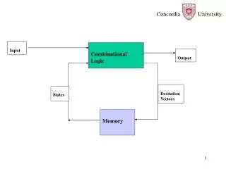
Real signal Im. signal Computer Digital/ analogue converter. Waveform controller ADC ~MHz 16 bit ADC ~MHz 16 bit 3 gradient coils ~10 mT/m RF pulse envelope kHz kHz kHz kHz Phase sensitive detector 1 Phase sensitive detector 2 Gradient Amplifiers Mixer multiplier MHz MHz MHz Pre Amp RF Amplifier ~10 kW MHz Magnet ~1.5 T MHz MHz RF coil ~10-5T 0o 90o Quadrature splitter Frequency synthesiser ~MHz (wo) MHz (wo)