Download
1 / 58
630 likes | 870 Vues
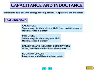
CAPACITANCE AND INDUCTANCE. Introduces two passive, energy storing devices: Capacitors and Inductors. LEARNING GOALS. CAPACITORS Store energy in their electric field (electrostatic energy) Model as circuit element. INDUCTORS Store energy in their magnetic field Model as circuit element .

E N D
CAPACITANCE AND INDUCTANCE Introduces two passive, energy storing devices: Capacitors and Inductors LEARNING GOALS CAPACITORS Store energy in their electric field (electrostatic energy) Model as circuit element INDUCTORS Store energy in their magnetic field Model as circuit element CAPACITOR AND INDUCTOR COMBINATIONS Series/parallel combinations of elements RC OP-AMP CIRCUITS Integration and differentiation circuits
CIRCUIT REPRESENTATION CAPACITORS First of the energy storage devices to be discussed Typical Capacitors Basic parallel-plates capacitor NOTICE USE OF PASSIVE SIGN CONVENTION
PLATE SIZE FOR EQUIVALENT AIR-GAP CAPACITOR Normal values of capacitance are small. Microfarads is common. For integrated circuits nano or pico farads are not unusual
Basic capacitance law Linear capacitors obey Coulomb’s law C is called the CAPACITANCE of the device and has units of One Farad(F)is the capacitance of a device that can store one Coulomb of charge at one Volt. Voltage across a capacitor of 2 micro Farads holding 10mC of charge EXAMPLE V Capacitance in Farads, charge in Coulombs result in voltage in Volts Linear capacitor circuit representation Capacitors can be dangerous!!!
Capacitors only store and release ELECTROSTATIC energy. They do not “create” LEARNING BY DOING The capacitor is a passive element and follows the passive sign convention Linear capacitor circuit representation
Capacitance Law DC or steady state behavior If the voltage varies the charge varies and there is a displacement current One can also express the voltage across in terms of the current … Or one can express the current through in terms of the voltage across Differential form of Capacitance law Integral form of Capacitance law The mathematical implication of the integral form is ... Implications of differential form?? A capacitor in steady state acts as an OPEN CIRCUIT Voltage across a capacitor MUST be continuous
CAPACITOR AS CIRCUIT ELEMENT LEARNING EXAMPLE Ohm’s Law The fact that the voltage is defined through an integral has important implications...
Instantaneous power Energy is the integral of power CAPACITOR AS ENERGY STORAGE DEVICE W If t1 is minus infinity we talk about “energy stored at time t2.” If both limits are infinity then we talk about the “total energy stored.”
Energy stored in 0 - 6 msec Charge stored at 3msec LEARNING EXAMPLE “total energy stored?” .... “total charge stored?” ... If charge is in Coulombs and capacitance in Farads then the energy is in ….
WHAT VARIABLES CAN BE COMPUTED? SAMPLE PROBLEM J Energy stored at a given time t C Charge stored at a given time A Current through the capacitor Electric power supplied to capacitor at a given time W J Energy stored over a given time interval
If the current is known ... SAMPLE PROBLEM Current through capacitor Voltage at a given time t Voltage at a given time t when voltage at time to<t is also known V C Charge at a given time Voltage as a function of time W Electric power supplied to capacitor V J Energy stored in capacitor at a given time “Total” energy stored in the capacitor J
SAMPLE PROBLEM Given current and capacitance Compute voltage as a function of time At minus infinity everything is zero. Since current is zero for t<0 we have In particular Charge stored at 5ms Total energy stored Before looking into a formal way to describe the current we will look at additional questions that can be answered. Total means at infinity. Hence Now, for a formal way to represent piecewise functions....
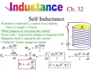
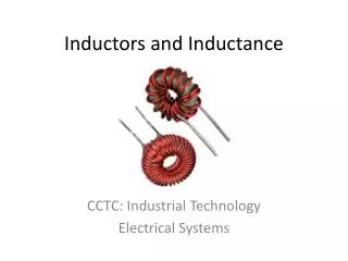
INDUCTORS NOTICE USE OF PASSIVE SIGN CONVENTION Circuit representation for an inductor Flux lines may extend beyond inductor creating stray inductance effects A TIME VARYING FLUX CREATES A COUNTER EMF AND CAUSES A VOLTAGE TO APPEAR AT THE TERMINALS OF THE DEVICE
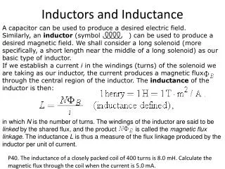
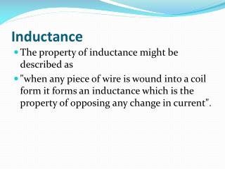
A TIME VARYING MAGNETIC FLUX INDUCES A VOLTAGE Induction law FOR A LINEAR INDUCTOR THE FLUX IS PROPORTIONAL TO THE CURRENT THE PROPORTIONALITY CONSTANT, L, IS CALLED THE INDUCTANCE OF THE COMPONENT DIFFERENTIAL FORM OF INDUCTION LAW INDUCTANCE IS MEASURED IN UNITS OF henry (H). DIMENSIONALLY LEARNING by Doing INDUCTORS STORE ELECTROMAGNETIC ENERGY. THEY MAY SUPPLY STORED ENERGY BACK TO THE CIRCUIT BUT THEY CANNOT CREATE ENERGY. THEY MUST ABIDE BY THE PASSIVE SIGN CONVENTION Follow passive sign convention
Differential form of induction law Integral form of induction law A direct consequence of integral form Current MUST be continuous A direct consequence of differential form DC (steady state) behavior Power and Energy stored W Current in Amps, Inductance in Henrys yield energy in Joules J Energy stored on the interval Can be positive or negative “Energy stored at time t” Must be non-negative. Passive element!!!
LEARNING EXAMPLE FIND THE TOTLA ENERGY STORED IN THE CIRCUIT In steady state inductors act as short circuits and capacitors act as open circuits
J THE DERIVATIVE OF A STRAIGHT LINE IS ITS SLOPE LEARNING EXAMPLE L=10mH. FIND THE VOLTAGE ENERGY STORED BETWEEN 2 AND 4 ms THE VALUE IS NEGATIVE BECAUSE THE INDUCTOR IS SUPPLYING ENERGY PREVIOUSLY STORED
L=0.1H, i(0)=2A. Find i(t), t>0 Energy stored on the interval Can be positive or negative SAMPLE PROBLEM ENERGY COMPUTATIONS Initial energy stored in inductor “Total energy stored in the inductor” Energy stored between 0 and 2 sec
FOR ENERGY STORED IN THE INDUCTOR LEARNING EXAMPLE FIND THE VOLTAGE ACROSS AND THE ENERGY STORED (AS FUNCTION OF TIME) NOTICE THAT ENERGY STORED AT ANY GIVEN TIME IS NON NEGATIVE -THIS IS A PASSIVE ELEMENT-
LEARNING EXAMPLE FIND THE CURRENT L=200mH
L=200mH POWER ENERGY FIND THE POWER NOTICE HOW POWER CHANGES SIGN FIND THE ENERGY ENERGY IS NEVER NEGATIVE. THE DEVICE IS PASSIVE
LEARNING EXTENSION L=5mH FIND THE VOLTAGE
LEARNING EXAMPLE GIVEN THE VOLTAGE WAVEFORM DETERMINE THE VARIATIONS IN CURRENT CAPACITOR SPECIFICATIONS
CURRENT WAVEFORM LEARNING EXAMPLE GIVEN THE CURRENT WAVEFORM DETERMINE THE VARIATIONS IN VOLTAGE INDUCTOR SPECIFICATIONS
IDEAL AND PRACTICAL ELEMENTS IDEAL ELEMENTS MODEL FOR “LEAKY” INDUCTORS MODEL FOR “LEAKY” CAPACITOR CAPACITOR/INDUCTOR MODELS INCLUDING LEAKAGE RESISTANCE
SERIES CAPACITORS Series Combination of two capacitors NOTICE SIMILARITY WITH RESITORS IN PARALLEL
LEARNING EXAMPLE ALGEBRAIC SUM OF INITIAL VOLTAGES POLARITY IS DICTATED BY THE REFERENCE DIRECTION FOR THE VOLTAGE DETERMINE EQUIVALENT CAPACITANCE AND THE INITIAL VOLTAGE OR WE CAN REDUCE TWO AT A TIME
SAME CURRENT. CONNECTED FOR THE SAME TIME PERIOD SAME CHARGE ON BOTH CAPACITORS Two uncharged capacitors are connected as shown. Find the unknown capacitance LEARNING EXAMPLE
PARALLEL CAPACITORS LEARNING EXAMPLE
FIND EQUIVALENT CAPACITANCE SAMPLE PROBLEM
SAMPLE PROBLEM IF ALL CAPACITORS HAVE THE SAME CAPACITANCE VALUE C DETERMINE THE VARIOUS EQUIVALENT CAPACITANCES
All capacitors are equal with C=8 microFarads Examples of interconnections
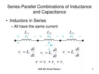
LEARNING EXAMPLE SERIES INDUCTORS
LEARNING EXAMPLE PARALLEL INDUCTORS INDUCTORS COMBINE LIKE RESISTORS CAPACITORS COMBINE LIKE CONDUCTANCES
LEARNING EXTENSION ALL INDUCTORS ARE 4mH CONNECT COMPONENTS BETWEEN NODES WHEN IN DOUBT… REDRAW! IDENTIFY ALL NODES PLACE NODES IN CHOSEN LOCATIONS
LEARNING EXTENSION SELECTED LAYOUT ALL INDUCTORS ARE 6mH NODES CAN HAVE COMPLICATED SHAPES. KEEP IN MIND DIFFERENCE BETWEEN PHYSICAL LAYOUT AND ELECTRICAL CONNECTIONS
RC OPERATIONAL AMPLIFIER CIRCUITS INTRODUCES TWO VERY IMPORTANT PRACTICAL CIRCUITS BASED ON OPERATIONAL AMPLIFIERS THE IDEAL OP-AMP
RC OPERATIONAL AMPLIFIER CIRCUITS -THE INTEGRATOR IDEAL OP-AMP ASSUMPTIONS
RC OPERATIONAL AMPLIFIER CIRCUITS - THE DIFFERENTIATOR KVL IDEAL OP-AMP ASSUMPTIONS IF R1 COULD BE SET TO ZERO WE WOULD HAVE AN IDEAL DIFFERENTIATOR. IN PRACTICE AN IDEAL DIFFERENTIATOR AMPLIFIES ELECTRIC NOISE AND DOES NOT OPERATE. THE RESISTOR INTRODUCES A FILTERING ACTION. ITS VALUE IS KEPT AS SMALL AS POSSIBLE TO APPROXIMATE A DIFFERENTIATOR DIFFERENTIATE
SIMPLE MODEL FOR A NOISY 60Hz SINUSOID CORRUPTED WITH ONE MICROVOLT OF 1GHz INTERFERENCE. noise signal THE DERIVATIVE signal noise ABOUT ELECTRIC NOISE ALL ELECTRICAL SIGNALS ARE CORRUPTED BY EXTERNAL, UNCONTROLLABLE AND OFTEN UNMEASURABLE, SIGNALS. THESE UNDESIRED SIGNALS ARE REFERRED TO AS NOISE