Download
1 / 48
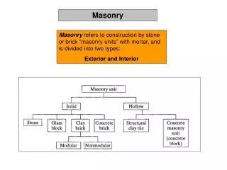
560 likes | 965 Vues
Set out masonry structures. Unit Outcomes : Interpreting given instructions to establish setting out work to be carried out. Selecting required quantity and quality of resources when setting out and building masonry structures

E N D
Set out masonry structures Unit Outcomes: Interpreting given instructions to establish setting out work to be carried out. Selecting required quantity and quality of resources when setting out and building masonry structures Assisting in the setting out and building of masonry structures to working drawings Mike Dixon
MATERIALS FOR SETTING OUT A BUILDING The following list would be for a small detached house: • plans and specifications • two measuring tapes (30m),preferably steel • optical level Mike Dixon
MATERIALS FOR SETTING OUT A BUILDING • site square (optional) • 50 mm × 50 mm timber pegs • 25 mm × 100 mm timber for profiles • lump hammer to knock in pegs • claw hammer Mike Dixon
MATERIALS FOR SETTING OUT A BUILDING • hand saw • a line • concrete (ballast and cement) to secure pegs (although sometimes unnecessary) • sand (for marking out trenches) Mike Dixon
MATERIALS FOR SETTING OUT A BUILDING • 50 mm round head nails • 75 mm round head nails. • The list is not exhaustive, but should give you some idea of what is required. Mike Dixon
RESOURCES FOR TRANSFERRING LEVELS Generally speaking most buildings are built level (horizontal) so it makes sense to do the setting out on a level plane. A building is kept level by various methods. Using datum points and Ordnance Survey bench marks (OBM) in transferring levels. Mike Dixon
RESOURCES FOR TRANSFERRING LEVELS The picture shows the position of the average sea level of the UK. This is called 0.000 metres and is taken from the average level of the sea in Newlyn, Cornwall. Marks are positioned countrywide (shown dotted) in relation to this sea level and are often carved in stone walls, churches, government buildings, or sometimes cast in a concrete pedestal Mike Dixon
RESOURCES FOR TRANSFERRING LEVELS The picture shows a datum with an ‘assumed’ level of 10.000 m. The floor level is 10.000 m so the floor level is the same as the datum. The bottom of the excavation is 9.000 m, so the excavation is 1.000 m below the datum peg. The top of the foundation concrete is 9.150 m. So the thickness of the foundation concrete is, 9.150 – 9.000 = 0.150 m. Mike Dixon
RESOURCES FOR TRANSFERRING LEVELS When the Ordnance Survey system is used for reference, the nearest OBM is used. Then a relative temporary bench mark (TBM), or site datum is positioned on site. It can be in the form of a steel or wooden peg set in concrete and is very often protected by a fence. Mike Dixon
SITE CLEARANCE AND HEALTH AND SAFETY A number of things need to be taken into consideration during the stages of setting out, such as: The tools and equipment required Digging the actual foundation, either by hand or using heavy plant equipment. Mike Dixon
SITE CLEARANCE AND HEALTH AND SAFETY The area where the structure is to be built could have been barren for a long time, and may have become a tipping ground for all kinds of rubbish such as glass, metal objects, even hypodermic needles. Therefore, great care should be taken when clearing the area ready to commence setting out. When putting pegs into the ground, remember that objects can be buried out of sight such as underground pipes and cables. Mike Dixon
SITE CLEARANCE AND HEALTH AND SAFETY Methane gas can also be a problem if the ground has been used previously for material excavation, such as sand or gravel, and then backfilled over the course of time for house construction. Some of these considerations would probably have been checked for at an earlier stage. But you should always be aware and take precautions such as wearing appropriate personal protective equipment. (PPE) Mike Dixon
LOCATING EXISTING SERVICES Before any excavations take place, whether it is digging out foundations or trenches for new drains, etc., a survey of the area must be carried out. This is done to find out whether there are any underground services in the area. These service could be: gas pipes water pipes Mike Dixon
LOCATING EXISTING SERVICES electricity cables telephone cables drainage pipes. Mike Dixon
LOCATING EXISTING SERVICES If a mechanical digger is carrying out the excavation, then damage to the service can happen extremely quickly. The digger bucket can go through the ground and the service without much effort. This can cause delays to the work due to the time it may take to carry out repairs to the damage, which will add extra cost to the project. Mike Dixon
LOCATING EXISTING SERVICES There will also be a great deal of inconvenience to the people in the surrounding area, who may be left with no electricity, gas, water, etc. for a long period of time while the service is being repaired. Service providers can’t always send out a repair crew immediately, and this inconvenience may go on for several days. Mike Dixon
PROCEDURES FOR SETTING OUT Setting out at the right place Finding the right place to set out sounds like an obvious thing to state, but it is very important that this is done absolutely correctly. Buildings have sometimes had to be completely demolished for being put up in the wrong place! This is because building lines and boundary lines are often involved, and there are very strict regulations governing these. Mike Dixon
PROCEDURES FOR SETTING OUT Mike Dixon
DIMENSIONAL ACCURACY It is most important that a building has square (90°) corners. Therefore, the setting out of a building must be square to avoid construction problems later. For example: Roof not fitting! Kitchen units not fitting! Mike Dixon
DIMENSIONAL ACCURACY Site square A site square is an optical instrument used to set out right angles simply and accurately. It is supported by a tripod. The body of the instrument contains two telescopes that are mounted at 90° to each other. The telescopes also pivot vertically so that various distances can be sighted. Mike Dixon
DIMENSIONAL ACCURACY Builder’s square A builder’s square is the most commonly used way of setting out a corner if no optical square is available on the site. It is made of timber or metal and obviously has to be practical enough to be easily carried and held in place for checking corners. Mike Dixon
DIMENSIONAL ACCURACY The 3:4:5 method A building can also be set out using the 3:4:5 method, which is a way of forming right angles using trigonometry. It may sound tricky, but the 3:4:5 rule is not very difficult to understand. Mike Dixon
DIMENSIONAL ACCURACY The 3:4:5 method If you take three straight lines, one 3 cm long, one 4 cm long and one 5 cm long, and then join them together to make a triangle, the angle opposite the longest line will always be a right angle. Mike Dixon
DIMENSIONAL ACCURACY How to set out a right angle using the 3:4:5 method Mike Dixon
METHODS FOR TRANSFERRING LEVELS Mike Dixon
METHODS FOR TRANSFERRING LEVELS This is a very basic method of transferring a level. Peg B is levelled from peg A (the datum) and then peg C is levelled from peg B. The straight edge and level are rotated 180° at each levelling point to eliminate any error in the level or straight edge. Transferring levels by spirit level and straight edge Mike Dixon
METHODS FOR TRANSFERRING LEVELS Optical level An optical level is a levelling device that comprises a camera, a tripod and a staff or grade rod. The camera swivels on a pin projecting from the top of the tripod. The average optical level is accurate to within 6 mm over a distance of approximately 30–40 m. Once placed in position on the tripod and adjusted for level, the optical level projects a level line across the distance between the datum peg and the point to which this datum level is to be transferred. Mike Dixon
TASK Watch the video and then proceed to use the optical level to transfer a level in the room Mike Dixon
METHODS FOR TRANSFERRING LEVELS Optical level Step 1 – securely position tripod and lower level onto pin. Step 2 – adjust optical level using the adjustment knobs at the base of the level. Ensure that the bubble is accurately positioned within the vial on the top of the level. Step 3 – position staff or grade rod on top of the datum peg and adjust focus on optical level until a clear reading can be made. Mike Dixon
METHODS FOR TRANSFERRING LEVELS Optical level Step 4 – take reading at the point where the crosshair of the viewfinder crosses the staff or grade rod. Optical level view Mike Dixon
METHODS FOR TRANSFERRING LEVELS Step 5 – get a second person to move staff to new location to where level is to be transferred. This location is identified by a peg driven into the ground and slightly extended in height to that of the original datum peg. Step 6 – second person holds staff or grade rod against the peg, with its markings or gradings facing the optical level. Mike Dixon
METHODS FOR TRANSFERRING LEVELS Optical level Step 7 – second person moves staff up or down on the instructions of the person using the optical level, until the same reading is established. Step 8 – second person marks base of the staff or grade rod on the peg. Step 9 – a timber rail can be fixed at this point to maintain the mark. The top of the timber rail will be lined across this mark to show the height of the transferred datum level. Transferred level Mike Dixon
Step-by-step guide to setting out a building • Make sure you know where the building line and boundaries are 2. Check your equipment before commencing 3. Establish a datum where it will not be disturbed Mike Dixon
Step-by-step guide to setting out a building 4. Always use measurements given and avoid scaling 5. Set out a base line (for example, front of a house). Make sure that you do not infringe on or over the building line 6. Be aware of any underground pipes, etc. Mike Dixon
Step-by-step guide to setting out a building 7. Check the drawings for errors 8. Take all measurements with care and accuracy 9. Check and double check setting out after completion. Mike Dixon
Step-by-step guide to setting out a building Step 1 – Establish frontage line 1. Peg A to Peg B. 2. Nails indicate corners of building. 3. Pegs reasonably level with each other. 4. Pegs must be secure and not move. Mike Dixon
Step-by-step guide to setting out a building • Step 2 – Establish peg C • Assume sizes are • 4 m × 2 m: • X² = 4² + 2² • X² = 16 + 4 • X² = 20 • X = √20 • X = 4.472 m • Two tapes can be used now from A and B to find C. Mike Dixon
Step-by-step guide to setting out a building Step 3 – Establish peg D 1. Use two tapes and measure from pegs C and B. 2. Check diagonals A–D and C–B. 3. Building is square if the diagonals are the same length Mike Dixon
Step-by-step guide to setting out a building Step 4 – Erect profiles at E and F 1. Project line from nails in pegs A and B. 2. Mark profiles with nail or saw cut. 3. Profiles should be 1 m minimum away from face – further if machine digging. Mike Dixon
Step-by-step guide to setting out a building Step 5 – repeat step 3 The profile at peg D showing alternative corner set out Mike Dixon
Step-by-step guide to setting out a building Step 6 – Remove corner pegs 1. Attach continuous line as shown. 2. Line represents face line(s). 3. Line should not ‘bind’ on crossing Mike Dixon
Step-by-step guide to setting out a building Step 7 – Edges of foundations marked on profiles 1. Line attached – plumbed down and marked on ground with sand (shown dotted). . 2. Trenches excavated Mike Dixon
Step-by-step guide to setting out a building Locating walling and trench positions As part of setting out, you must accurately locate walling and trench positions onto both single wall and corner type profiles. Mike Dixon
Step-by-step guide to setting out a building Once the centre lines have been established onto the profiles, the trench positions and wall positions can be marked onto them, using the drawing and specification to determine the cavity size, wall thicknesses and foundation width. Mike Dixon
Step-by-step guide to setting out a building These measurements can then be added to the profile by the use of nails or saw cuts. Mike Dixon
Step-by-step guide to setting out a building Space between profiles and excavations The working space required between profiles depends on the method of excavation. When machines are used in excavations, There needs to be space to allow the machines to move. If trenches are to be dug out by machine, the spoil either has to be put into piles within reach of the bucket arm or carried away using a dumper. In this case, if the profiles are too close together they may be damaged or run over by the machines Mike Dixon
Step-by-step guide to setting out a building If the foundation is going to be dug by hand, less room will be needed as the spoil is removed by wheelbarrow. Mike Dixon
Step-by-step guide to setting out a building Transferring setting out information onto foundation concrete Marking wall positions onto concrete can be done by using spray paint, chalk or mortar to mark position lines. Use a level to plumb down onto the concrete foundation, with the top of the level just about touching the line. Mike Dixon