Download
1 / 19
190 likes | 200 Vues
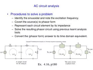
Engineering Circuit Analysis. CH7 Magnetically Coupled Circuits. 7.1 Self-inductance and mutual inductance 7.2 Dot convention 7.3 Transformer. Ch7 Magnetically Coupled Circuits. Physical phenomenon:

E N D
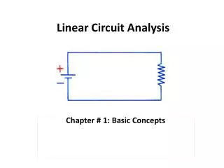
Engineering Circuit Analysis CH7 Magnetically Coupled Circuits 7.1 Self-inductance and mutual inductance 7.2 Dot convention 7.3 Transformer
Ch7 Magnetically Coupled Circuits • Physical phenomenon: By having two closely located coils, the magnetic flux created by one coil will affect the other – leading to the mutual inductance. • Voltage across a coil is introduced by the self inductance and mutual inductance. • Application: The transformer – coverts the ac voltage to a higher or lower value required by the load.
v1 + v1 i1 i1 - Ch7 Magnetically Coupled Circuits 7.1Self-inductance and mutual inductance Coupled Circuitsand v ~ i relationship Magnetic flux: 1 = f(i1) (1 = N11) The flux is proportional to the current in linear inductor: 1(t) = L1i1(t) L is a lumped element abstraction for the coil.
+ + v1 v2 - - i2 i1 Ch7 Magnetically Coupled Circuits 7.1Self-inductance and mutual inductance Coupled Circuitsand v ~ i relationship ——Ideal Coupled Circuits’v ~ i relationship • L1、L2、Mrepresent Ideal Coupled Inductor, Self inductance Mutual inductance
+ + v2 v1 + + v1 - - - - i2 i2 i1 i1 Ch7 Magnetically Coupled Circuits 7.1Self-inductance and mutual inductance Coupled Circuitsand v ~ i relationship v2
• • • • v1 v1 v2 v2 + + + + v2 v1 v1 v2 - - - - i2 i2 i2 i2 i1 i1 i1 i1 Ch7 Magnetically Coupled Circuits 7.2 Dot Convention A current entering the dotted terminal of one coil produces an open circuit voltage with a positive voltage reference at the dotted terminal of the second coil.
Example Ch7 Magnetically Coupled Circuits 7.2 Dot Convention Apply dot convention , M creates a negative potential at the dot position of the primary mesh Apply dot convention , M creates a negative potential at the dot position of the secondary mesh
• • • v2 v1 v2 v1 u2 • Suppose direction of the i and is consistent with Dot convention! i2 i2 1.For self-inductance voltage 2.For mutual-inductance voltage - + - + - + - + - + i1 i1 - + - + - + + - - + Ch7 Magnetically Coupled Circuits 7.2 Dot Convention Question:The terminal is dotted,how can we get v ~ iequations to coupled inductor? Steps to determine the coupled circuit voltage :
P4.16,For the circuit shown in following figures, determine v1andv2. i1 i2 i2 i1 i2 i1 M M M - • • • L1 • L2 v1 v2 v1 v2 v1 v2 L2 u2 u2 u2 L1 L2 L1 • • + Ch7 Magnetically Coupled Circuits 7.2 Dot Convention
+ + v1 v2 - - i2 i1 For sinusoidal circuit, Ch7 Magnetically Coupled Circuits 7.2 Dot Convention Coupled Circuitsand v ~ i relationship ——Ideal Coupled Circuits’s v ~ i relationship
- + Primary mesh : + - Secondary mesh : Ch7 Magnetically Coupled Circuits 7.2 Dot Convention • Example (Practice 10.2, p267)
Example10.2 (KVLS for the three meshes) ( ~ Ch7 Magnetically Coupled Circuits 7.2 Dot Convention Mesh 1 : Mesh 2 : Mesh 3 :
In the equivalent network, mutual inductance no longer exists. And the dot convention has been removed. , and are also treated as self-inductance. Ch7 Magnetically Coupled Circuits 7.3 Transformer Equivalent networks---- equivalent network
A C Apply the original transformer: D B C A B D Apply the equivalent network: Ch7 Magnetically Coupled Circuits 7.3 Transformer • Example10.4 (P274) One the equivalence : Let Let
Ch7 Magnetically Coupled Circuits 7.3 Transformer ---- equivalent network (※)
Ch7 Magnetically Coupled Circuits 7.3 Transformer -- ideal transformer Turn ratio Number of turns of wire forming the coil
Ch7 Magnetically Coupled Circuits 7.3 Transformer KVL for both primary and secondary meshes V1 = jwL1I1 – jwMI2 0 = -jwMI1 + (ZL + jwL2)I2 With
Ch7 Magnetically Coupled Circuits 7.3 Transformer Impedance Matching Condition of maximizing the power that is being transferred One can apply the ideal transformer to have the above matching to be achieved. if if Current and voltage adjustment
Determine Knowing , the equivalent impedance of the resistor in the primary mesh is : Hence , Ch7 Magnetically Coupled Circuits 7.3 Transformer Thevenin equivalent for mesh 1 : Example 10.6 (P281) Thevenin equivalent for mesh 2 :