Download

1 / 39
390 likes | 624 Vues
Status of VIRGO A. Freise For the Virgo Collaboration European Gravitational Observatory SPIE Glasgow 2004. The VIRGO Collaboration. V IRGO is an Italian-French collaboration for Gravitational Wave research with a ground - based interferometer. ITALY - INFN Firenze-Urbino Frascati

E N D
Status ofVIRGO • A. Freise • For the Virgo Collaboration • European Gravitational Observatory • SPIE Glasgow 2004
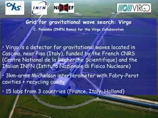
The VIRGO Collaboration VIRGO is an Italian-French collaboration for Gravitational Wave research with a ground-based interferometer. • ITALY - INFN • Firenze-Urbino • Frascati • Napoli • Perugia • Pisa • Roma • FRANCE - CNRS • ESPCI – Paris • IPN – Lyon • LAL – Orsay • LAPP – Annecy • OCA - Nice
The European Gravitational Observatory Last mirror installed June 2003 Inauguration August 2003
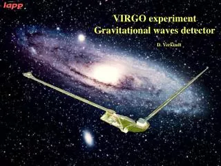
The VIRGO Interferometer Input Mode Cleaner 144 m long Michelson Interferometer with3 km long Fabry-Perot cavitiesin the arms and Power Recycling Output Mode Cleaner 4 cm long • High quality optics are: • located in vacuum • suspended from multi-stage pendulums Laser 20 W
Main Optics High quality fused silica mirrors • 35 cm diameter, 10 cm thickness • Substrate losses 1 ppm • Coating losses <5 ppm • Surface deformation l/100 (rms on 150mm) • DR: <10-4
Vacuum System • Two tubes: 3 km long, 1.2 m in diameter, installed and tested, in vacuum since June 2003, 10-6 mbar • All tower (6 long, 2 short) pumping systems: installed, tested and put in operation, 10-9 mbar Towers Tubes
The Suspension System The Superattenuator (SA) is designed toisolate the optical components from seismic activities (local disturbances). It is based on the working principle of a multistage pendulum. Expected attenuation @10 Hz:1014 Residual mirror motion (rms) rotation <1 mrad longitudinal<1 mm
The Top Stage Top of an inverted pendulum: - Inertial damping (70 mHz to 5 Hz) - Possibility to move the suspension point with small forces
Passive Filters • Five seismic filters: • Suspended by steel wires • Vertical isolation by a combination of cantilever springs and magnetic anti-springs
The Local Control Marionette control:CCD camera, optical levers and fourcoil-magnet actuators: <2 Hz
Fast Control (Global) Reference mass and mirror,four coil-magnet actuators: >2 Hz
Laser Master Slave • Located on an optical table outside the vacuum • Nd:YAG master commercial CW single mode (700 mW) @1064 nm • Phase locked to a Nd:YVO4 slave (monolithic ring cavity) • Pumped by two laser diodes at 806 nm (40 W power) • Output power: 20 W
Input Mode Cleaner • Triangular cavity, 144 m long, Finesse=1000 • Input optics and two flat mirrors are located on a suspended optical bench • End mirror suspended with a reference massfor actuation • Transmission 50% Injection Bench Mode Cleaner Mirror
Detection System Output Mode-Cleaner • Suspended bench in vacuum with optics for beam adjustments and the output mode cleaner (OMC) • Detection, amplification and demodulation on external bench Suspended bench External bench
Output Mode Cleaner Output Mode-Cleaner • 4 cm long ring cavity • Suppression of TEM01 by a factor of 10 • Length control via temperature (Peltier element) • Lock acquisition takes 10 min, lock accuracy is l/60000 Detection Bench
Photo Diodes Output Mode-Cleaner • 16 InGaAs diodes for the main beam (dark port) • 6 additional photo diodes (and 8 split photo diodes) for control purposes External bench
Control • Fully digital control, local and global • Feedback is send with 20-bit DACs @ 10kHz to thesuspensions • The suspension control is performed by decicated DSPs (one per suspension) • Interferometer signals are acquired with 16-bit ADCs @ 20 kHz. The data is transferred via optical linksto Global Control, a dedicated hard and software that computes correction signals and sends them to the mirror DSPs
Computer Control Monitoring and control of the detector by scientists and operators using: - 10 workstations - a digital video system
Current Status Central Interferometer (CITF) • Commissioning of the central interferometer and the injection system from 2001 to 2003 • Since September 2003 commissioning of the two arms and the full interferometer • At the end of this year the detector is planned to be operated in its final configuration • Scientific data taking starts 2005
Commissioning of VIRGO The commissioning of the full detector is divided into three phases: Phase A: the 3 km long arm cavities separatly Phase B: recombined Michelson interferometer Phase C: Michelson interferometer with Power Recycling Currently we have completed phase B.
Commissioning Runs Continuous data taking periods are scheduled every second month: • C1: 14.-17. November 2003 • North arm cavity longitudinally controlled • C2: 20.-23. February 2004 • North arm cavity with longitudinal and angular control • C3: 23.-27. April 2004 • Recombined interferometer • North arm with second stage of frequency stabilisation • C4: 24.-29. June 2004 • Recombined interferometer with angular control and second stage of frequency stabilisation
Sensing and Control • Modulation-demodulation • scheme with only one modulation frequency • (6 MHz) to control: • 4 lengths • 10 angles
Phase A: the two arm cavities are used separatly, starting with the north arm; control systems are to be installed and tested. North Arm Cavity West arm misaligned PR misaligned
In October 2003 the North arm cavity was locked on first trial using a control algorithm that was tested before with SIESTA, a time domain interferometer simulation The West arm cavity was locked in December 2003 North Arm Cavity
North Arm Sensitivity • Sensitivity limited by frequency noise between 7 Hz and 4 kHz (C1) • By reducing the bandwidth of the IMC control loops the frequency noise could be improved • The noise below 4 kHz (C3) still originates in the injection system but is not fully understood
Recombined Interferometer • Phase B: • Recombined Interferometer • B2 (P) used to control common mode (L1+L2) • B2 (Q) used to control beam splitter • - B1/B1’ used to control differential mode (L1-L2) Recombined locked in February 2004 PR misaligned
Automatic Alignment • Anderson technique: • - Modulation frequency coincident with cavity TEM01 mode • - Two split photo diodes in transmission of the cavity (at two different Guoy phases) • - Four signals to control the 2x2 mirror angular positions (NI, NE)
Automatic Alignment • Alignment control allows to switch off local controls • Power inside the cavities becomes more stable • Installed and tested for the recombined interferometer • Bandwidth ~3 Hz • Residual fluctuations ~0.5 urad rms (1 nrad @ 10 Hz)
The laser frequency is stabilised to the common lengths of thearm cavities (bandwidth ~17 kHz) The arm cavities are stabilised to the reference cavity (bandwidth ~2 Hz) Gains of the frequency control loops are increased Frequency stabilisation The `second stage´ of frequency stabilisation
Frequency stabilisation • The pre-stabilisation of the laser frequency was succesfully tested in the central interferometer • The frequency noise of the pre-stabilised laserlimits the sensitivity over a wide range • The second stage required for the designed stability was completed in June 2004 • The performance will be tested in the commissioning run (C4) starting today
Conclusions • The construction of VIRGO is finished, the commissioning of the full instrument is underway • Both arm cavities were put into operation, longitudinal and angular control were implemented • The injection system and the detection system withboth mode cleaners are used routinely during thecommissioning • The detector is now used in the recombined mode with automatic mirror alignment and the second stage of frequency stabilisation • Starting next week the final configuration including Power Recycling will be implemented • The first scientific data runs are planned for next year
Data Acquisition and Storage • 16-bit ADCs, up to 20 kHz sampling frequency • Data is transferred via optical linksto workstations and then written to disk in Frame format:- full signal- down-sampled to 50 Hz- down-sampled to 1 Hz (trend data) • Frames available for data monitoringwith 3 s delay • Current rate: 7 Mbytes/s (compressed) • On-site storage on spinning media: - 5 TB for online analysis- 70 TB for offline analysis
Injection System • 20 W Nd:YAG master-slave laser • Input mode cleaner: 144 m long ring cavity • Reference cavity: 30 cm long ring cavity, mirrors contacted to a rigid ULE spacer • Both cavities: Finesse=1000 IMC RFC
Recombined Interferometer Sensitivity below 300 Hz limited by electronic noise from a temporary sensor setup