Download
1 / 30
360 likes | 580 Vues
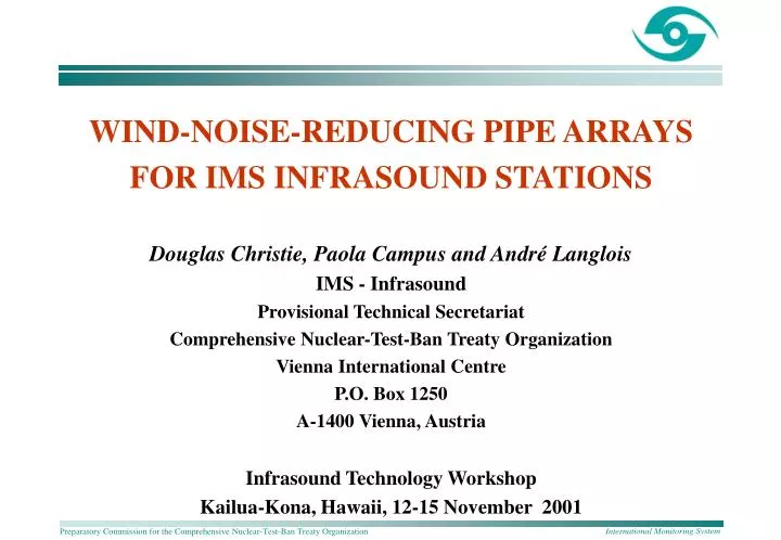
WIND-NOISE-REDUCING PIPE ARRAYS FOR IMS INFRASOUND STATIONS Douglas Christie, Paola Campus and André Langlois IMS - Infrasound Provisional Technical Secretariat Comprehensive Nuclear-Test-Ban Treaty Organization Vienna International Centre P.O. Box 1250 A-1400 Vienna, Austria

E N D
WIND-NOISE-REDUCING PIPE ARRAYS FOR IMS INFRASOUND STATIONS Douglas Christie, Paola Campus and André Langlois IMS - Infrasound Provisional Technical Secretariat Comprehensive Nuclear-Test-Ban Treaty Organization Vienna International Centre P.O. Box 1250 A-1400 Vienna, Austria Infrasound Technology Workshop Kailua-Kona, Hawaii, 12-15 November 2001
OUTLINE • Summary: Wind Noise at IMS Infrasound Stations • Review of Current PTS Pipe Array Designs • Performance Characteristics • Limitations • Basic Design Requirements for Pipe Arrays • Improved Pipe Array Configurations for High-Wind Environments • Elimination of Resonances • Initial Experimental Results • Conclusions
VERY LOW WIND ENVIRONMENTS • Mean Wind Speed: < 1.0 m/s • Stations located in equatorial rainforest • Require only small diameter pipe arrays • ~ 12% of all IMS stations IS39 Palau
LOW WIND ENVIRONMENTS • Mean Wind Speed: 1 to 2.5 m/s • Stations located inside temperate forests • Require 18-m diameter pipe arrays at all sites • ~ 32% of all IMS stations IS10 Lac du Bonnet, Canada
MODERATE WIND ENVIRONMENTS • Mean Wind Speed: 2.5 to 4 m/s • Stations located in open fields, semi-desert areas, etc. with some vegetation cover (bushes, tall grass, small trees) • Require larger diameter pipe arrays (up to 70 m) • ~ 33% of all IMS stations IS07 Warramunga, Australia
HIGH WIND ENVIRONMENTS • Mean Wind Speed: 4 to 6 m/s • Stations located in exposed areas with no significant vegetation cover • Require larger diameter pipe arrays • ~ 17% of all IMS stations • Further work required on the development of suitable pipe arrays for high wind environmentsIS19 Djibouti
VERY HIGH WIND ENVIRONMENTS • Mean Wind Speed: > 6 m/s • Arctic and Antarctic stations, stations located in exposed areas with very high winds. • ~ 6% of all IMS stations • Will require large diameter pipe arrays. • Suitable wind-noise-reducing pipe arrays need to be developed. IS18 Qaanaaq, Greenland
PIPE ARRAYS: CURRENT PTS DESIGNS Low Wind Speed Environments (< 2.5 m/s) • 18-m, 96-port pipe array • Designed for use at sites located inside forests • Effective at higher frequencies (> 0.1 Hz) • Fairly good performance in high winds for frequencies > 1 Hz • Low resistance screened inlet ports • Resonance at ~11 Hz
PIPE ARRAYS: CURRENT PTS DESIGNS Moderate Wind Speed Environments (< 4 m/s) • 36-m and 70-m diameter pipe arrays • Very good performance for winds of < 4 m/s in frequency range from about 0.05 to 1 Hz (70-m) and 0.07 to 2 Hz (36-m) • Poor performance at higher frequencies due to resonances at ~2.5 Hz (70-m), ~5 Hz (36-m)
LIMITATIONS: CURRENT PIPE ARRAY DESIGNS • Distribution of inlet ports is not optimal. • Ports should be uniformly distributed. • Number of inlet ports should be as large as possible. • 18-m and 70-m diameter pipe arrays have resonances that distort higher frequency signals. • This is a serious problem. • All pipe arrays with distributed inlet ports distort high frequency signals. • Cut-off frequency for 70-m diameter arrays is about 4 Hz. • Cut-off frequency for 18-m diameter arrays is about 16 Hz.
IMPROVED PIPE ARRAY DESIGNS DESIGN REQIREMENTS • Diameter of pipe array should be as small as possible. • Ports should be arranged to uniformly cover the area around the sensor. • The distance between adjacent ports should be as large as possible. • All ports should be equally effective. • Maximum efficiency can be achieved using designs based on a close-packed-hexagonal configuration.
CLOSE-PACKED HEXAGONAL PIPE ARRAYS SMALLER PIPE ARRAY DESIGNS
CLOSE-PACKED HEXAGONAL PIPE ARRAYS LARGER PIPE ARRAY DESIGNS
COMPARISON OF PIPE ARRAYS Close-Packed Hexagonal Configuration Current PTS Design Distance between ports ~ 1.8 m Distance between ports ~ 0.8 m • Close-packed hexagonal design will have significantly better performance in higher winds and at lower frequencies. 92 ports 90 ports
CLOSE-PACKED HEXAGONAL PIPE ARRAY WITH SINGLE SUMMING MANIFOLD • Inlet ports are arranged on a close-packed hexagonal grid • Discrete inlet ports are connected directly by a single pipe to the primary summing manifold. • Variations in connecting pipe lengths will reduce influence of resonances.
RESONANCES IN PIPE ARRAYS • Fundamental problem that results in signal distortion near the resonance frequency. Elimination of Resonances in Pipe Arrays: • Use of sufficiently long length of porous garden hose. • Mode conversion: Change open pipe configuration to an effectively closed pipe configuration. This will shift the resonances to higher frequencies that may lie outside the passband of interest. • Suitable high impedance baffles inserted into pipes will also shift pipe resonances to higher frequencies. • Other techniques, such as the use of tapered pipes, which eliminate reflections at the ends of the pipes.
ELIMINATION OF RESONANCES USING POROUS HOSES Advantages • Porous garden hose connected to an impermeable pipe provides an effective means for the elimination of pipe array resonances (Hedlin and Berger, 2001; Herrin et al., 2001; Garces and Hetzer, 2001). • Porous hose pipe arrays are relatively inexpensive and can be installed rapidly. • Resonances in both small and large diameter pipe arrays can be eliminated using porous hose. • Effective wide-band noise reduction can be achieved using a suitably designed large diameter porous hose pipe array.
ELIMINATION OF RESONANCES USING POROUS HOSES Problems with Porous Hoses • Porous hoses are not robust. They are easily damaged by animals and fire. • The properties of porous hoses installed in hot desert environments change with time. Porous hoses become brittle when exposed to high levels of ultraviolet radiation and the porosity degrades. • Porous hoses are not suitable for use in tropical wet rainforest environments. The hoses become saturated with moisture and may cease to function. • The properties of porous hoses will be affected by rain, groundwater flow, mud and dust. • Porous hoses do not appear to be suitable for use at IMS stations in Antarctica and at high-latitude stations in the Arctic.
POROUS HOSES: DAMAGE BY ANIMALS, AGEING AND FIRE • Porous hoses installed at WRAI in Australia were observed to sag and split along the side after two years. • Other hoses at this station were destroyed by fire. • Porous hoses used in the infrasound site survey at IS01 Ushuaia were damaged by native rat bites.
USE OF POROUS HOSES AT IMS INFRASOUND STATIONS CONCLUSIONS • Unprotected porous hoses will require extensive maintenance and may need to be replaced at frequent intervals. • It may be possible to provide some protection from animals, precipitation, ultraviolet radiation, dust and mud by installing porous hoses inside perforated pipes (preferably metal) mounted slightly above ground level or by installing the hoses inside a layer of gravel on the surface. • Porous hoses do not appear to be suitable for permanent use at many IMS infrasound stations.
ELIMINATION OF PIPE ARRAY RESONANCES BY MODE CONVERSION • Conversion from an open pipe system to an effectively closed pipe system will shift resonances to higher frequencies. • This can be accomplished in discrete-port pipe arrays by inserting a high acoustic impedance between the open screened inlet port and the connecting pipe. • Screened inlet ports provide useful noise reduction at high frequencies and guarantee that the high acoustic impedances cannot be blocked by insects, spiders and other small animals and by dust and dirt. • Inline acoustic impedances with values of 0.3, 28, 142 and 357 cgs acoustic ohms have been tested by the PTS. • Initial tests indicate that the 0.3 cgs ohm devises are not useful. Higher value impedances increase the resonant frequencies.
MODIFIED SCREENED INLET PORT 357 cgs ohm impedance connected to screened inlet port
RESONANT MODE CONVERSION AT A 22-METER DIAMETER, 8-PORT EXPERIMENTAL PIPE ARRAY a)Open-port configuration b) Effectively closed pipe configuration with 357 cgs ohm inlet ports Fundamental resonance has lower amplitude and occurs at higher frequency.
RESONANT MODE CONVERSION AT AN 18-METER DIAMETER IMS PIPE ARRAY 357 cgs ohm impedances installed on the inlet ports at site H4 at IS26 Freyung, Germany
RESONANT FREQUENCY SHIFT: 18-METER DIAMETER IMS PIPE ARRAY 357 cgs ohm impedances installed on the inlet ports at site H4 at the Freyung, Germany infrasound array Position of resonance peak at ~ 11 Hz in open-port pipe system at array element H3 Open pipe system at H3 Position of attenuated resonance peak at ~ 22 Hz in closed pipe system at array element H4 IS26 Closed pipe system at H4 with 357 cgs ohm ports
INFLUENCE OF RESONANCES ON INFRASONIC SIGNAL WAVEFORMS Open port array 357 cgs ohm ports
Open port array Open port array Open port array 357 cgs ohm port array Open port array INFLUENCE OF RESONANCES ON INFRASONIC SIGNAL WAVEFORMS
(a) (b) (c) ELIMINATION OF RESONANCES USING HIGH IMPEDANCE BAFFLES 72-m, 2-Port Pipe Array Experiments (a) Open pipe array with open screened inlet ports. (b) Effectively closed pipe array with 142 cgs ohm inlet ports. (c) Effectively closed pipe array with 142 cgs ohm inlet ports and inline 142 ohm baffles inserted midway along each array arm pipe.
CONCLUSIONS • Pipe arrays based on a close-packed hexagonal configuration will have improved performance characteristics. • Resonances in existing wind-noise-reducing pipe array designs may distort higher-frequency infrasonic signals. • Resonances can be eliminated using either porous garden hose or suitably designed high impedance inlet ports and inline baffles. • Wind-noise-reducing pipe arrays used at IMS infrasound arrays should perform reliably under all conditions. Porous garden hose does not appear to be suitable for use at many IMS infrasound stations. • Further work needs to be undertaken on the development of suitable wind-noise-reducing pipe arrays for use in high wind environments.