Download
1 / 15
150 likes | 247 Vues
EI=10^7 L =100 =0.01 P =1.0. Ex 4.12. Transformation Matrix. Ex 4.13. 4.2.3 Generalized Coordinate Models for Specific Problems. Choice of mathematical models ; i.e, each element as bar, beam, plate, solid…. In Ex. 4.6.

E N D
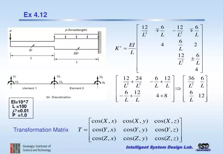
EI=10^7 L =100 =0.01 P =1.0 Ex 4.12 Transformation Matrix
4.2.3 Generalized Coordinate Models for Specific Problems Choice of mathematical models ; i.e, each element as bar, beam, plate, solid… In Ex. 4.6 Polynomials are used to approximate disp since they are easy to differentiate to get strain. (The higher the degree the better the approx ) More effective FE are isoparametric formulation.
Elementary Beam(Technical) Kirchhoff Plate Shear correction factor : k Reissner-Mindlin Plate Timoshenko Beam
Kirchhoff theory - Shear deformations are neglected. - The straight line remains normal to the midsurface during deformation. Reissner –Mindlin theory - Shear deformation are included. - The straight line remains straight and in general not normal to the midsurface during deformation. Flat rectangular shell element :
For more whose adjacent element is almost coplanar such as folded plate or curved shell , the stiffness matrix is singular or ill-conditioned. Therefore it is difficult to solve for equilibrium. To avoid this problem, add a small stiffness is in direction, i.e ,
k Factors for various Cross Sections ( Cowper ,G.R., J of applied mechanics , June, 1966,p335)
A FE solution should converge as the number of elements is increased to the analytical solution of the DE of mathematical model. monotonic convergence Errors : Round-off, time integration, iteractive, mode selection, linearization, discretization PVW
u1 u2 v2 v1 u2 u1 w2 v2 w1 v1 u2 u1 Monotonic convergence : Elements must be complete① and compatible②① complete : Displacements of FE should represent the rigid body displacement and the constant strain state ② compatible : Displacements within and across the elements must be continuous Number of element rigid body mode = Element DOF – Number of element straining mode (natural mode)
Calculation of Stresses Compatible (conforming) displacement and their derivatives are continuous.Displacement continuity does not mean stress continuity.Coarse FE model more difference.Reason : compatibility and constitutive equation are exactly satisfied while stress equilibrium are approximated.Thus Stresses in general more accurate at integration points than at the modal point. Hence, for a least square fit , use higher order functions than that of stresses from the assumed displacement function ( ) Average nodal stress = bilinearly extrapolate from Gauss point stress and then average Least square procedure requires more computation than average scheme NASTRAN ABAQUS s s m,b m,b
4.4 Incompatible(nonconforming) and mixed FE In displacement–based FEM, the assumed displacement function are complete and compatible. Those solution converges in the SE monotonically to the exact solution.For shell problem, compatibility is hard to maintain. Incompatible displacement-based models Relax compatibility condition No guarantee of monotonic convergence.Note that the size of FE gets smaller, each element should approach a constant strain condition. Patch test ( BM Irons & A Razzague ) Boundary nodal forces (or displacement BC ) constant stress For displacement–based incompatible elements, if the patch test is passed, convergence is insured