Download

1 / 43
620 likes | 966 Vues
DC otor & H Bridge. 1. Outline. DC Motor. Principle Speed Control. H Bridge. Control Power. Figure 1. Real DC Motors. 2. Principle Recap. Figure 2. Lorentz Force Direction. Figure 3. Loop Current Diagram. http://hyperphysics.phyastr.gsu.edu/hbase/magnetic/magmom.html. 3.

E N D
Outline DC Motor Principle Speed Control H Bridge Control Power Figure 1. Real DC Motors 2
Principle Recap Figure 2. Lorentz Force Direction Figure 3. Loop Current Diagram http://hyperphysics.phyastr.gsu.edu/hbase/magnetic/magmom.html 3
Rotational Speed Assume it is a 6V motor - + 6V Figure 5. Macro View + - 6V Figure 4. Voltage and Full Speed Rotation commons.wikimedia.org 4
Rotational Speed Assume it is a 6V motor + - 6V Figure 5. Macro View + - 6V Figure 4. Reverse Voltage and Rotation commons.wikimedia.org 5
Rotational Speed Assume it is a 6V motor + - 4V Figure 5. Macro View + - 4V Figure 4. Small Voltage and Slow Rotation commons.wikimedia.org 6
Speed Control PWM % Duty Cycle ↓↓ % AVG Voltage ↓↓ % Speed http://forum.xda-developers.com/showthread.php?t=2542054 Figure 6. PWM Timing Diagram 7
But… Drive? VCC: ~3.3V Current: ~10mA Backwards? http://www.hennkwell.com.tw/products.php?func=p_detail&p_id=39&pc_parent=8 Table 1. Specification of DC Gear Motor 8
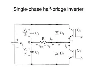
H Bridge Figure 7. H Bridge Diagram (http://en.wikipedia.org/wiki/H_bridge) Table 2. H Bridge Functions (http://en.wikipedia.org/wiki/H_bridge) 9
H Bridge Figure 7. An H Bridge Diagram Table 2. H Bridge Functions 10
H Bridge Figure 7. An H Bridge Diagram Table 2. H Bridge Functions 11
H Bridge Figure 7. An H Bridge Diagram Table 2. H Bridge Functions 12
H Bridge Figure 7. An H Bridge Diagram Table 2. H Bridge Functions 13
H Bridge Figure 7. An H Bridge Diagram Table 2. H Bridge Functions 14
H Bridge Figure 7. An H Bridge Diagram Table 2. H Bridge Functions 15
H Bridge Figure 7. An H Bridge Diagram Table 2. H Bridge Functions 16
H Bridge Figure 7. An H Bridge Diagram Table 2. H Bridge Functions 17
L298N Block Diagram Figure 8. L298N Block Diagram (L298N Datasheet) 18
L298N Block Diagram (Left Half) Figure 9. L298N Block Diagram (Left Half) (L298N Datasheet) 19
Four Switches in H Bridge Figure 9. L298N Block Diagram (Left Half) (L298N Datasheet) 20
H Bridge’s Shape Figure 7. H Bridge Diagram (http://en.wikipedia.org/wiki/H_bridge) Figure 9. L298N Block Diagram (Left Half) (L298N Datasheet) 21
Power Supply Figure 7. H Bridge Diagram (http://en.wikipedia.org/wiki/H_bridge) Figure 9. L298N Block Diagram (Left Half) (L298N Datasheet) 22
Logic Power Supply Figure 7. H Bridge Diagram (http://en.wikipedia.org/wiki/H_bridge) Figure 9. L298N Block Diagram (Left Half) (L298N Datasheet) 23
Inputs and Enable Figure 7. H Bridge Diagram (http://en.wikipedia.org/wiki/H_bridge) Figure 9. L298N Block Diagram (Left Half) (L298N Datasheet) 24
M Outputs Figure 7. H Bridge Diagram (http://en.wikipedia.org/wiki/H_bridge) Figure 9. L298N Block Diagram (Left Half) (L298N Datasheet) 25
Functions M S1 S3 1 S4 S2 0 1 Figure 9. L298N Block Diagram (Left Half) (L298N Datasheet) Table 2. H Bridge Functions (http://en.wikipedia.org/wiki/H_bridge) 26
Functions M S1 S3 0 S4 S2 1 1 Figure 9. L298N Block Diagram (Left Half) (L298N Datasheet) Table 2. H Bridge Functions (http://en.wikipedia.org/wiki/H_bridge) 27
Functions v M S1 S3 X S4 S2 X 0 Figure 9. L298N Block Diagram (Left Half) (L298N Datasheet) Table 2. H Bridge Functions (http://en.wikipedia.org/wiki/H_bridge) 28
Functions M S1 S3 0 S4 S2 0 1 Figure 9. L298N Block Diagram (Left Half) (L298N Datasheet) Table 2. H Bridge Functions (http://en.wikipedia.org/wiki/H_bridge) 29
Functions M S1 S3 1 S4 S2 1 1 Figure 9. L298N Block Diagram (Left Half) (L298N Datasheet) Table 2. H Bridge Functions (http://en.wikipedia.org/wiki/H_bridge) 30
Functions M S1 S3 S4 S2 Figure 9. L298N Block Diagram (Left Half) (L298N Datasheet) Table 2. H Bridge Functions (http://en.wikipedia.org/wiki/H_bridge) 31
Functions M S1 S3 S4 S2 Figure 9. L298N Block Diagram (Left Half) (L298N Datasheet) Table 2. H Bridge Functions (http://en.wikipedia.org/wiki/H_bridge) 32
Functions M S1 S3 S4 S2 Figure 9. L298N Block Diagram (Left Half) (L298N Datasheet) Table 2. H Bridge Functions (http://en.wikipedia.org/wiki/H_bridge) 33
An example 40V http://www.eecs.umich.edu/eecs/courses/eecs373/labsW14/lab6/index.html http://www.motioncontroltips.com/2013/05/06/30mm-dc-motor-from-maxon/ Figure 12. SmartFusion FPGA Figure 10. 30mm DC Motor from Maxon Figure 11. SN754410 Pin Connections (SN754410 Datasheet) GND 34
What if we want to use a large-powered motor? 50V http://www.motioncontroltips.com/2013/05/06/30mm-dc-motor-from-maxon/ Figure 10. 30mm DC motor from maxon Figure 13. L298N Pin Connections (L298N Datasheet) It will likely burn the H-bridge! 35
Voltage Constraint (L298N) https://www.sparkfun.com/datasheets/Robotics/L298_H_Bridge.pdf Table 3. Voltage Constraint for L298N • DC voltage cannot exceed H-bridge voltage constraint 36
Power Constraint (SN754410) http://www.ti.com/lit/ds/symlink/sn754410.pdf Table 4. Voltage Constraint for SN754410 37
What if we want to use that large-power DC motor? Build an H-bridge with 4 switches! 38
Which switch shall we use? • BJT • (Bipolar Junction Transistor) • Easier to build, use less circuitary • Good for low current operation VS • MOSFET • (Metal–Oxide–Semiconductor • Field-Effect Transistor) • Good for high current operation http://www.eeweb.com/electronics-forum/how-this-h-brigde-is-working http://www.youtube.com/watch?v=A_JNjAFo1f4&list=PLXrSeSVAb819HfhysOtYMdwDg3CTKXi6B Figure 15. H-bridge with MOSFET Figure 14. H-bridge with BJT 39
What is BJT? What is MOSFET? Don’t need to know http://fourier.eng.hmc.edu/e84/lectures/ch4/node3.html http://robertdick.org/eecs312/lectures/dic-l5.pdf PNP – active low NPN – active high NMOS – active high PMOS – active low Choose voltage/current wisely on gate/base 40
How to use BJT? C B E http://blog.oscarliang.net/bjt-bipolar-junction-transistor-beginner-tutorial/ http://www.eeweb.com/electronics-forum/how-this-h-brigde-is-working Figure 16. BJT Model Figure 17. H-bridge with BJT 41
How to use MOSFET? PMOS NMOS http://airsofttutorials.com/tutorials/diy-mosfet.html http://www.youtube.com/watch?v=A_JNjAFo1f4&list=PLXrSeSVAb819HfhysOtYMdwDg3CTKXi6B Figure 18. MOSFET Model Figure 19. H-bridge with MOSFET Connect PMOS to Vcc, NMOS to ground 42
Reference DC Motor: Basic Principle: http://hyperphysics.phy-astr.gsu.edu/hbase/magnetic/motdc.html http://en.wikipedia.org/wiki/DC_motor Speed Control with PWM: http://www.youtube.com/watch?v=NqqgbS3KXz0 Shaft Encoder https://www.anaheimautomation.com/manuals/forms/magnetic-encoder-guide.php H Bridge http://en.wikipedia.org/wiki/H_bridge L298N Datasheet: https://www.sparkfun.com/datasheets/Components/General/L298N.pdf SN754410 Datasheet: http://www.ti.com/lit/ds/symlink/sn754410.pdf 43