Download
1 / 1
10 likes | 119 Vues
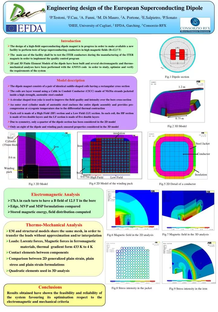
insulation. Steel Cylinder (35mm thick). 1.2 m. Steel Jacket. Iron. Iron. Conductor. 0.6 m. Winding pack. 0.75 m. Insulation. bore. 0.075m. High Field. Low Field. Engineering design of the European Superconducting Dipole.

E N D
insulation Steel Cylinder (35mm thick) 1.2 m Steel Jacket Iron Iron Conductor 0.6 m Winding pack 0.75 m Insulation bore 0.075m High Field Low Field Engineering design of the European Superconducting Dipole 1P.Testoni, 1F.Cau, 1A. Fanni, 1M. Di Mauro, 2A. Portone, 2E.Salpietro, 3P.Sonato 1DIEE, University of Cagliari, 2 EFDA, Garching, 3 Consorzio RFX Introduction • The design of a high-field superconducting dipole magnet is in progress in order to make available a new facility to perform tests of large superconducting conductors in high magnetic fields (B=12.5 T) • The main use of the facility shall be to test the ITER conductors during the manufacturing of the ITER magnets in order to implement the quality control program • 2D and 3D Finite Element Models of the dipole have been built and several electromagnetic and thermo-mechanical analyses have been performed with the ANSYS code in order to study, optimize and verify the requirements of the system Fig.1 Dipole section Model description • The dipole magnet consists of a pair of identical saddle-shaped coils having a rectangular cross section • The coils are layer wound using a Cable in Conduit Conductor (CICC) made of Nb3Sn strands jacketed inside a high strength, austenitic steel conduit • A circular shaped iron yoke is used to improve the field quality and intensity over the bore cross-section • An outer steel cylinder made of austenitic steel encloses the entire dipole assembly and provides pre-compression at cryogenic temperature due to the differential thermal contraction • Each coil is made of a High Field (HF) section and a Low Field (LF) section. In each coil, the HF section is made of two double layers and the LF section is made of five double layers • Due to symmetry, only a quarter of the dipole section has been considered in the 2D model • Only an eight of the dipole and winding pack smeared properties considered in the 3D model Fig.2 3D Model Fig.4 2D Model of the winding pack Fig.3 2D Model Fig.5 2D Detail of a conductor • Electromagnetic Analysis • 17kA in each turn to have a B field of 12.5 T in the bore • Edge, MVP and MSP formulations compared • Stored magnetic energy, field distribution computed • Thermo-Mechanical Analysis • EM and structural models share the same mesh, in order to transfer the loads without approximation and/or interpolation • Loads: Lorentz forces, Magnetic forces in ferromagnetic materials, thermal gradient form 433 K to 4 K • Contact elements between components • Comparison between 2D generalized plain strain, plain stress and plain strain formulations • Quadratic elements used in 3D analysis Fig.7 Magnetic field in the 3D analysis Fig.6 Magnetic field in the 2D analysis Conclusions Fig.8 Stress intensity in the jacket Fig.9 Stress intensity in the iron Results obtained have shown the feasibility and reliability of the system favouring its optimisation respect to the electromagnetic and mechanical criteria