Download
1 / 27
270 likes | 421 Vues
Week 10. Other Construction Drawings. Objective. This chapter gives an overview of building systems and the drawings that represent them, specifically demolition, plumbing, heating, ventilation and air conditioning, and site plans. Electrical Plans. Figure 13-2 Electrical plan for a kitchen.

E N D
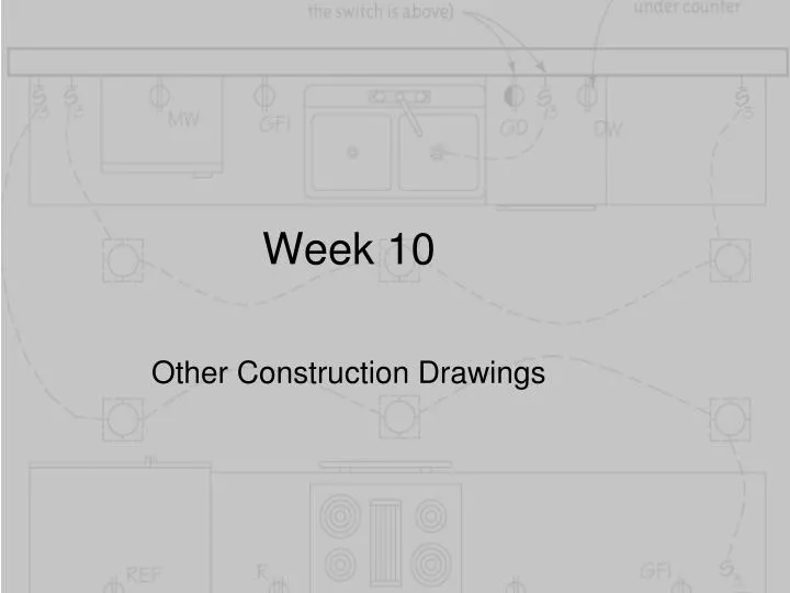
Week 10 Other Construction Drawings
Objective • This chapter gives an overview of building systems and the drawings that represent them, specifically demolition, plumbing, heating, ventilation and air conditioning, and site plans
Electrical Plans Figure 13-2 Electrical plan for a kitchen
Electricity and its Delivery • Electricity is the flow of electrical power • Generated at a power plant using fuel • Fuel sources include: • Coal, oil, and nuclear raw materials • Solar, wind, and combustible gas from landfills • Decomposing corn stalks
Electricity and its Delivery (cont’d.) Figure 13-6 How electricity is delivered within the house
Electrical Terms • Flow of electrons: current measured in amps • Household electrical consumption measured in kilowatt (1000 watts) abbreviated kW • Total amount of electrical energy used is measured in kilowatt-hours (kWh) • kWh: work performed by one kilowatt in one hour
Electric meter measures amount of energy customer uses Electrical Terms (cont’d.) Figure 13-7 Residential electric watt-hours meter
Electrical Terms (cont’d.) • Service panel • Receives electricity into the house from the service entrance or meter box • Distributes it throughout via branch circuits • Large metal box • Contains circuit breakers or fuses • Circuit • Includes the conductor, switching device(s), and the outlet for a load
Electrical Terms (cont’d.) • Voltage: pressure that forces electrons through a wire • Current: flow of electrons through a wire, measured in amperes • Appliance: general term for any item powered through a plug and a flexible cable • Watt: unit of power, calculated as energy per unit of time • Lamp: technical term for light bulb
Electrical Terms (cont’d.) Fixture: consists of map, reflector, opening, housing, and connection to power source May contain ballast to regulate power Conduit: hollow tube that holds conductors Switch: electrical device that opens and closes circuit Types: toggle, push-button, dimmer, timer, joystick, single-pole, three-way, four-way
Electrical Terms (cont’d.) Convenience outlet: receptacle; connection device Ground fault circuit interrupter (GFCI): safety device installed on circuit Ground: electrical connection to earth Special outlets: phone jacks, TV antenna jacks, alarm systems, etc. Automated systems: low-voltage, electronically controlled devices
Drawing the Electrical Plan Figure 13-14 Drafting common electrical symbols
Power/Telephone/Data/VOIP Plans • Shows where electrical outlets, phone jacks, data ports, computers, video equipment, and communications systems are located • Includes the following: • Data ports • Digital subscriber lines • Telephony (includes Voice over IP) • Communication systems
Reflected Ceiling Plan • View of the ceiling as if it were reflected onto a mirror that is flat on the floor • Shows ceiling materials, molding, ornamentation, exposed structural elements, HVAC, soffits, exposed beams, skylights, building grid lines, and anything else that is on or touches the ceiling
Reflected Ceiling Plan (cont’d.) Figure 13-27 Rich ornamentation is described on a refracted ceiling plan.
Shows HVAC systems Drawings: mechanical and equipment plans Includes furnaces, air conditioners, water heaters, ducts, filters, humidifiers, pipes, control devices, outlets registers and vents Climate Control Plans
Climate Control Terms Natural gas: energy source for gas-fueled furnaces Furnace: appliance that produces heat Air conditioner: appliance that cools, filters, and dehumidifies air Heat pump: appliance that heats and cools a building Thermostat: regulates temperature in a furnace or air conditioner via sensors and activating switches
Climate Control Terms (cont’d.) • Zone: specific area heated or cooled by one unit • Hydronic: heating or cooling system that transfers heat via a circulating fluid • Pipes: copper tubes round in cross-section, that serve as the distribution method in hydronic systems • Humidifier: appliance that adds moisture to the house
Climate Control Terms (cont’d.) • Ducts: distribution and return-air path in a forced-air system • Register: outlet in a forced-air system through which air is returned to a room • Forced-air heat systems: furnace draws room air through ductwork and returns the warmed air to the rooms • Flexible tubes and panels heat system: radiant system
Reading the Mechanical Plan Figure 13-42 Examples of the pipes and fittings that mechanical symbols and plans schematically represent
Plumbing Plans Figure 13-43 Plumbing plan
Water heater PEX: cross-linked polyethylene Water pipes Fixture Trap: S-shaped section of pipe Valve: controls flow Stack: vertical pipe Stack wall Clean-out Plumbing Terms
Well Main Hose bib Septic tank Sump pump Freshwater water delivery Waste water discharge Plumbing Terms (cont’d.)
Demolition Plans Figure 13-60 Demolition plan
Site Plans • North arrow: shows the solar orientation of the house • Engineer scale: used to dimension the property • Footprint: building’s shape, size and orientation • Property lines: physical boundaries • Hard surfaces: include walks, entries, driveways, access roads, and patios • Waterways: include rivers and lakes
Site Plans (cont’d.) • Utility lines: include gas, electricity, water, and sewer lines • Vegetation: comprises trees and shrubs • Contour lines: show ground elevations • Legal description: includes location of the property lines • Details: construction drawings • Related drawings: survey, plots, landscape plans
Summary • Many different types of drawings are included in a set of instructions for constructing or renovating a building • Floor plans, elevations, sections, details, electrical, water, and building systems drawings are all necessary to describe the design • While the interior designer may not draw all of them, it is useful to be able to read them and recognize key features