Download
1 / 19
340 likes | 838 Vues
Vertical-Axis Wind Turbine. Kang Zheng Aaron Peterson Mohd Ramjis. Presentation Outline. Project Objective Background/Design Description Structural Analysis Fabrication Process Future Work Conclusion Questions. Project Objective.

E N D
Vertical-Axis Wind Turbine Kang Zheng Aaron Peterson MohdRamjis
Presentation Outline • Project Objective • Background/Design Description • Structural Analysis • Fabrication Process • Future Work • Conclusion • Questions
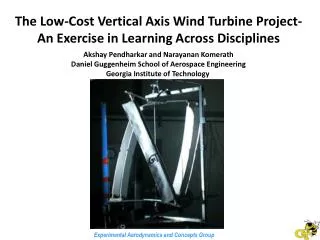
Project Objective • To design, build, and test composite airfoil blades for a wind turbine.
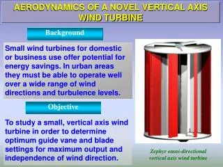
Background • A wind turbine is a rotating machine which converts kinetic energy in wind to electrical energy. • The use of wind turbine is important as it is the alternative to other main energy generators. • There are two major types of wind turbine determined based on the axis in which the turbine rotates. • Horizontal Axis Wind Turbine (HAWT) • Vertical Axis Wind Turbine (VAWT)
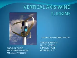
Design Description • Vertical Axis Wind Turbine • The main rotor shaft arranged vertically • Consists of three vertical airfoil blades made of composite with each blade has a helical twist of 120 degrees • Blades mounted on aluminum flat plate
Design Description • Why we chose this design? • Tolerates higher wind speed • Airfoil constantly in the direction of wind; reduce noise and cyclic loading • Higher airfoil pitch angle (improves aerodynamics, decreases drag) • Be located nearer to ground
Structural Analysis • The aluminum plate were designed in a circular fashion with arcs cut out (120 deg) to reduce weight while maintaining stability • Analysis performed on the aluminum plate by applying centrifugal force on the axis of rotation • Blades were designed for a twisted angle of 120 degrees • Simplified air pressure as pressure force on inner surface of the blade
Structural Analysis • Displacement • 1200 rpm 100 psi stress 0.355’’ disp.
Structural Analysis Displacement 300 rpm 2.231e-6’’ disp. 17.38 psi stress
Scale Model • Graphite/Epoxy composite with a foam core blade • Length: 35 in. • Height of capture area: 27.5 in. • 3 in. chord foam core • 1/16” Aluminum sheets • 24 in. diameter circle • Shaft • 60 in. long, 1 in. diameter Aluminum shaft • Support structure • 4x4 in. wood cross sections
Fabrication Process We started by cutting out small templates of the airfoil out of wood Using these, we cut out foam cores of the airfoils for us to wrap the fibers around. • After each ply was laid, and epoxy was applied, we wrapped the mold with release film and added the vacuum tube.
Fabrication Process • After the composites cured, we took the plastic off to make sure that each blade cured correctly. • We trimmed the excess fibers and epoxy off of the blade, and then sanded it to make the airfoil create more drag.
Fabrication Process • The bolts were fixed into the ends of the blades. • After the blades were completed, we constructed the aluminum plates for the top and bottom supports
Results • What did we want? • Rotational speed vs. wind speed • Drag on the assembly • Why were we unable? • Time constraints • Limited access to AABL wind tunnel • Lack of funding • Tool limitations
Future Work • Future work: • Add an alternator, voltmeter, pulley, and v-belt for power generation calculation • Add electrical system for the wind turbine • Wind tunnel testing • Optimize: • Weight • Airfoil shape • Angle of attack
Conclusion • Wind turbines are going to be in high demand as the switch to renewable energy is in progress • The blades made out of composite materials have greatly reduced the weight of the entire assembly • The composite blades also allow the structure of the support be manufactured out of lighter, and more cost effective materials
References • Special thanks to: • Nathan Knop (T.A) • Tom Elloitt (Technician) • Bill Rickard (Technician) • VinayDayal (Project advisor)