Download
1 / 31
310 likes | 433 Vues
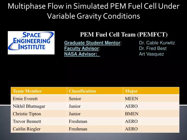
Multiphase Flow in Simulated PEM Fuel Cell Under Variable Gravity Conditions. PEM Fuel Cell Team (PEMFCT). Graduate Student Mentor : Dr. Cable Kurwitz Faculty Advisor : Dr. Fred Best NASA Advisor: Art Vasquez. Presentation Outline. Background Objectives - NASA’s Needs - SEI Goals

E N D
Multiphase Flow in Simulated PEM Fuel Cell Under Variable Gravity Conditions PEM Fuel Cell Team (PEMFCT) Graduate Student Mentor: Dr. Cable Kurwitz Faculty Advisor: Dr. Fred Best NASA Advisor: Art Vasquez
Presentation Outline • Background • Objectives • - NASA’s Needs • - SEI Goals • Review of Fall Work • Preliminary Analysis • Review of Spring Work • Ground Testing • Set Up • Manufacturing • PSA • Preliminary Modeling • Results • New Direction • Conclusions
What is a Fuel Cell? • Typical fuel cells generate electricity by combining a fuel and oxidizer in the presence of an electrolyte • Main parts of a fuel cell • Flow channels for fuel and oxidizer • Anode and Cathode separated by an electrolyte • Fuel and oxidizer react to produce electricity and byproducts • Fluid distribution and control is a critical issue with fuel cell operation • The parallel flow channels and parallel plates can produce flow instabilities leading to degraded fuel cell operation and possible damage • Goal –Identify regions of operation where instabilities can occur
Objectives • NASA’s Need • Utilized fuel cells in Gemini, Apollo, and currently in Space Shuttle • NASA plans to utilize fuel cells in Constellation program • Technology has many other applications • Vehicles, buildings, and alternative energy applications • Purpose • Evaluate flow conditions that lead to unstable operation within a prototypic fuel cell geometry • Develop a flow map that describes stable and unstable operating regions • Provide simple modeling approach to predict transition from stable to unstable operation • Learning Objectives: • Understand two-phase fluid flow • Identify and understand the flow conditions that produce instabilities
Fall Semester Activties • Literature Review • Understood fuel cells and the flow distribution during operation as well as flow anomalies • Researched standard geometries and flow rates • Confirmed with NASA Advisor • Developed CAD drawings of two cell geometries • Performed stress and flow analysis for both parallel and serpentine configurations • Built simple cells for ground testing • Proposed testing to Microgravity University
Cosmos FloWorks Velocity Analysis Parallel Plate Gas Used: Nitrogen Mass Flow Rate: 3 SLPM Inlet Pressure: 50 psig Inlet Temperature: 293.2 K Max Channel Velocity: 0.1 m/s
Cosmos FloWorks Velocity Analysis Serpentine Plate Gas Used: Nitrogen Mass Flow Rate: 3 SLPM Inlet Pressure: 50 psig Inlet Temperature: 293.2 K Max Channel Velocity: 0.35 m/s
Cosmos FloWorks Pressure Analysis Parallel Model Serpentine Model Gas Used: Nitrogen Mass Flow Rate: 3 SLPM Inlet Pressure: 50 psig Inlet Temperature: 293.2 K Parallel Model Delta Pressure: 10 Pa Serpentine Model Delta Pressure: 56 Pa
Stress Analysis Maximum Stress: 834.9 psi Located over channel/plenum junction. Maximum Displacement: <1 micron Located at lid over the plenum. Minimum Factor of Safety: 36 Maximum Stress: 274.3 psi Located at center of channel/plenum junction. Maximum Displacement: 10.82 microns Located over the center of the plenum. Minimum Factor of Safety: 110
Microgravity University - Reduced Gravity Student Flight Opportunities Program • Allows undergraduate teams to carryout flight testing of experiments in microgravity conditions • - Submitted Proposal • - Completed Safety Analysis • - Pursued Funding • - Education Outreach • Team Proposal Turned Down • Switch from NASA to Zero-G aircraft greatly reduced the number of experiments
Spring Semester Activities • Looked for alternative flight opportunities • FAST Program – decided not to pursue • Designed and fabricated a higher fidelity prototype to more accurately reflect fuel cell flow distribution • Uniform liquid addition throughout each channel • Built test loop for ground testing • Composed and submitted PSA • Performed preliminary testing and analysis
Parallel Plate Dimensions: 20 cm x 20 cm x 1 cm Channel Dimensions: 1 mm x 1mm Number of Channels: 80 Wetted Surface Area: 10,700 mm^3 NASA interest fueled by these being the standard geometries for fuel cells (based on chemical properties) Zoomed in View
Serpentine Plate Dimensions: 20 cm x 20 cm x 1 cm Channel Dimensions: 1 mm x 1mm Number of Channels: 20 Wetted Surface Area: 10,700 mm^3 Zoomed in View
Higher Fidelity Prototype • Added a liquid plenum for water • introduction from the bottom • 6 mm deep • Added holes along the channels • connecting the lumen of the channels • to the liquid plenum • Changed water input to directly • in the center for more • uniform addition
Flow Loop Schematic Flow Loop Schematic • Specifications • Gas provided by high pressure Nitrogen Tank • Regulated to 50 psig • Pressure Transducer will monitor pressure drop • Parallel Mass flow meters will simulate excess cells • CCD Digital Camcorders will record fluid instabilities • Vortex Water Separator will separate fluid from gas
Ground Test Package • Flow Loop Consists of 2 Flow Meters, Pressure Gauge, Differential Pressure Transducer, and CCD • Gas Flow Provided by Compressed Nitrogen Cylinder and Water Flow Provided by Liquid Syringe Pump • Test Stand Allows Cell Plate to be Rotated • PSA Written and Provided to Safety Officer
Ground Testing • Data is collected by video, flow meter and pressure gauge • Varied flow rate on primary flow meter from 0 to 10 sLPM • Bypass Flow Rate Varied from 0 to 90% of Primary Flow • Liquid Flow Rate 0 to 100 cc/min • Variation in gas and liquid flow rates occurred simultaneously
Results • Flow instabilities occur at all flow rates tested for parallel and serpentine channel fuel cell plates • Oscillations are small and focused toward exit of channels • Overall liquid holdup is constant for each test but varies over range of testing with large amounts of water held at low gas flow rates • Some channels occluded for duration of tests (No flow)
Results • Liquid holdup in channels varied with tilt angle on test article • Due to flow regime and hydrostatic pressure changes • Indicates a need for reduced gravity testing • Two-phase flow in outlet line seemed to have an effect on bypass flow
Lessons Learned • Liquid pores too large allowing gas to enter liquid plenum at high channel differential pressure • Graded pores or a more controlled method of adding water to better simulate water production is needed • New test setup required to accommodate water entering bypass flow meter
Learning Experiences • - Engineering Skills: • Analysis Tools • Solid Works, Cosmos FloWorks, CosmosWorks, Microsoft Visio • Analytic techniques to validate computation • Analysis of test data (i.e. model fitting) • Lab Skills: • Machining experience • Interpreting engineering drawings • Developing procedures • Carrying out test • Education Outreach • Teamwork
Conclusion • Purpose: -Evaluate flow conditions within a prototypic fuel cell geometry - Determine a range of stable operations for given flow and environmental conditions • Ground testing showed occlusions have a great gravitational dependence and that more work needs to be done on our test system
Future Work • Replace flow meter to complete ground test matrix • Modify test stand to allow higher flow rates • Modify liquid addition method to provide a more uniform liquid addition • Continue work on test loop and develop more robust analysis techniques
Preliminary Modeling • Parallel channel instability may occur when a number of channels are connected at common headers. • Although the total flow remains constant, flow oscillations may occur in some of the channels. • Nonlinear transient momentum equations can be used to solve for several channels by integrating the momentum equation along each channel. • Fluid properties used in the momentum equations are obtained from the energy equation and the equation of state. • The modeling is very complex , the following equations convey the complexity • After integrating the momentum equations for the channels, the equations are solved simultaneously.
Preliminary Modeling • Starting with the Momentum Equation • Define B and C • We Simplify
Preliminary Modeling • The Total Inlet Flow • Differentiating • We can then Solve n Equations to Determine the Channel Flow Rate