Download
1 / 131
1.33k likes | 1.56k Vues
Advanced Computer Architecture CSE 8383. February 7 2008 Session 4. Contents. Group Work Dependence Analysis Instruction Pipelines and hazards (revisit) ILP Multithreading Multiprocessors. Group Activity. C.V. State Diagram. Simple Cycles. Throughput (t = 20 ns). MAL. Greedy Cycles.

E N D
Advanced Computer ArchitectureCSE 8383 February 7 2008 Session 4
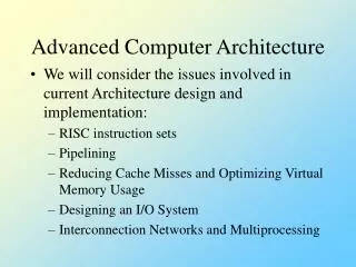
Contents • Group Work • Dependence Analysis • Instruction Pipelines and hazards (revisit) • ILP • Multithreading • Multiprocessors
Group Activity C.V State Diagram Simple Cycles Throughput (t = 20 ns) MAL Greedy Cycles
A B C D E F G H I Types of Dependencies • Name dependencies • Output dependence • Anti-dependence • Data True dependence • Control Dependence • Resource Dependence
Name dependences • Output dependence When instruction I and J write the same register or memory location. The ordering must be preserved to leave the correct value in the register i: add r7,r4,r3 j: div r7,r2,r8 • Anti-dependence When instruction j writes a register or memory location that instruction i reads i: add r6,r5,r4 j: sub r5,r8,r11
An instruction j is data dependent on instruction i if either of the following hold: instruction i produces a result that may be used by instruction j , or instruction j is data dependent on instruction k, and instruction k is data dependent on instruction i Data Dependences i i: add r6,r5,r4 j: sub r1,r6,r11 r6 j
Control Dependences A control dependence determines the ordering of an instruction i, with respect to a branch instruction so that the instruction i is executed in correct program order. If p1 { S1; }; If p2 { S2; };
Resource dependences An instruction is resource-dependent on a previously issued instruction if it requires a hardware resource which is still being used by a previously issued instruction. div r1, r2, r3 div r4, r2, r5
Removing name dependences (Register renaming) • Read-Write dependency (anti) DIV.D F0, F1, F2 (I1) ADD.D F3, F0, F4(I2) SUB.D F4, F5, F6 (I3) MUL.D F3, F5, F4 (I4) • I3 can not complete before I2 starts as I2 needs a value in F4 and I3 changes F4 • Remember? An anti-dependence exists if an instruction uses a location as an operand while a following one is writing into that location; • if the first one is still using the location when the second writes into it, an error occurs:
Register Renaming • Output dependencies and anti-dependencies can be treated similar to true data dependencies as normal conflicts, by delaying the execution of a certain instruction until it can be executed • Parallelism could be improved by eliminating output dependencies and anti-dependencies, which are not real data dependencies • These artificial dependencies can be eliminated by automatically allocating new registers to values, when such dependencies has been detected • This technique is called register renaming
Register Renaming • DIV.D F0, F1, F2 DIV.D F0, F1, F2 • ADD.D F3, F0, F4 ADD.D F3, F0, F4 • SUB.D F4, F5, F6 SUB.D T, F5, F6 • MUL.D F3, F5, F4 MUL.D S, F5, T
Linear Instruction Pipelines Assume the following instruction execution phases: • Fetch (F) • Decode (D) • Operand Fetch (O) • Execute (E) • Write results (W)
Pipeline Instruction Execution F D O E W Time
Pipeline Execution Cycles I1 I2 I3 I4 I5
Cycles Superscalar Execution (sneak preview) I1 I2 I3 I4 I5 I6
Pipeline & Hazards CPI = Ideal pipeline CPI + Structural Stalls + Data Hazard Stalls + Control Stalls • Ideal pipeline CPI: Maximum performance attainable by the implementation • Structural hazards: HW cannot support this combination of instructions • Data hazards: Instruction depends on result of prior instruction still in the pipeline • Control hazards: Caused by delay between the fetching of instructions and decisions about changes in control flow (branches and jumps)
Solutions • Structural Hazards solutions: • Have as many functional units as needed • Data Hazards solutions: • Execute instructions in order. Use score-board to eliminate data hazards by stalling instructions • Execute instructions out or order, as soon as operands are available, but graduate them in order. • Use register renaming to avoid WAR and WAW data hazards • Control Hazards solutions: • Use branch prediction: Make sure that the branch is resolved before registers are modified
ILP Architectures • Computer Architecture: is a contract (instruction format and the interpretation of the bits that constitute an instruction) between the class of programs that are written for the architecture and the set of processor implementations of that architecture. • In ILP Architectures: + information embedded in the program pertaining to available parallelism among instructions and operations in the program
ILP Architectures Classifications • Sequential Architectures: the program is not expected to convey any explicit information regarding parallelism. (Superscalar processors) • Dependence Architectures: the program explicitly indicates the dependences that exist between operations (Dataflow processors) • Independence Architectures: the program provides information as to which operations are independent of one another. (VLIW processors)
Sequential Architecture and Superscalar Processors • Program contains no explicit information regarding dependencies that exist between instructions • Dependencies between instructions must be determined by the hardware • Compiler may re-order instructions to facilitate the hardware’s task of extracting parallelism
Superscalar Processors • Superscalar processors attempt to issue multiple instructions per cycle • Essential dependencies are specified by sequential ordering so operations must be processed in sequential order • Could be a performance bottleneck
Dependence architecture and Dataflow Processors • The compiler (programmer) identifies the parallelism in the program and communicates it to the hardware (specify the dependences between operations) • The hardware determines at run-time when each operation is independent from others and perform scheduling • Objective: execute the instruction at the earliest possible time (once input operands and functional units are available).
Dataflow Processors • Dataflow processors are representatives of Dependence architectures • Execute instruction at earliest possible time subject to availability of input operands and functional units • Dependencies communicated by providing with each instruction a list of all successor instructions • As soon as all input operands of an instruction are available, the hardware fetches the instruction • Few Dataflow processors currently exist
Independence Architecture and VLIW Processors • By knowing which operations are independent, the hardware needs no further checking to determine which instructions can be issued in the same cycle • The set of independent operations >> the set of dependent operations Only a subset of independent operations are specified • The compiler may additionally specify on which functional unit and in which cycle an operation is executed The hardware needs to make no run-time decisions
VLIW processors • Operation versus Instruction Operation: is a unit of computation (add, load, branch = instruction in sequential architecture) Instruction: set of operations that are intended to be issued simultaneously • Compiler decides which operation to go to each instruction (scheduling) • All operations that are supposed to begin at the same time are packaged into a single VLIW instruction
VLIW strengths • In hardware it is very simple: consisting of a collection of function units (adders, multipliers, etc.) connected by a bus, plus some registers and caches • More silicon goes to the actual processing (rather than being spent on branch prediction, for example) • It should run fast, as the only limit is the latency of the function units themselves. • Programming a VLIW chip is very much like writing microcode
VLIW limitations • The need for a powerful compiler • Increased code size arising from aggressive scheduling policies • Larger memory bandwidth and register-file bandwidth • Limitations due to the lock-step operation, binary compatibility across implementations with varying number of functional units and latencies
Static Scheduling boosted by parallel code optimization Dynamic Scheduling without static parallel code optimization Dynamic Scheduling boosted by static parallel code optimization ILP Scheduling • done by the compiler • The processor receives dependency-free and optimized code for parallel execution • Typical for VLIWs and a few pipelined processors (e.g. MIPS) • done by the processor • The code is not optimized for parallel execution. The processor detects and resolves dependencies on its own • Early ILP processors (e.g. CDC 6600, IBM 360/91 etc.) • done by processor in conjunction with parallel optimizing compiler • The processor receives optimized code for parallel execution, but it detects and resolves dependencies on its own • Usual practice for pipelined and superscalar processors (e.g. RS6000)
What is Superscalar? • A machine designed to improve the performance of scalar instructions; where one instruction per cycle • Superscalar architecture allows several instructions to be issued and completed per clock cycle • It consists of a number of pipelines that are working in parallel. • Common instructions (arithmetic, load/store, conditional branch) can be initiated and executed independently in different pipelines. They are executed in an order different from the program order • Equally applicable to RISC & CISC, In practice usually RISC
IM Reg DM Reg ALU IM Reg DM Reg ALU IM Reg DM Reg ALU IM Reg DM Reg ALU IM Reg DM Reg ALU IM Reg DM Reg ALU Pipelined Execution
IM Reg DM Reg ALU IM Reg DM Reg ALU IM Reg DM Reg ALU IM Reg DM Reg ALU IM Reg DM Reg ALU IM Reg DM Reg ALU Superscalar Execution
How Does it Work? instruction fetch fetching of multiple instructions at once dynamic branch prediction & fetching beyond branches instruction issue methods for determining which instructions can be issued the ability to issue multiple instructions in parallel instruction commit methods for committing several instructions in fetch order duplicate & more complex hardware
$f2 $f4 $f6 y + + v $f10 $f4 $f8 w * $f10 z + x + $f10 v $f12 w x (inorder) y z Superscalar Execution Example Data Flow Critical Path = 9 cycles Assumptions • Single FP adder takes 2 cycles • Single FP multiplier takes 5 cycles • Can issue add & multiply together • Must issue in-order (Single adder, data dependence) (In order) v: addt$f10, $f2, $f4 w: mult$f10, $f10, $f6 x: addt$f12, $f10, $f8 y: addt$f4, $f4, $f6 z: addt$f10, $f4, $f8 13
$f2 $f4 $f6 v y + + v w $f10 x $f4 $f8 w * y z $f10 z + x + $f10 $f12 Out of Order Issue v: addt $f10, $f2, $f4 w: mult $f10, $f10, $f6 x: addt $f12, $f10, $f8 y: addt $f4, $f4, $f6 z: addt $f10, $f4, $f8 Critical Path = 9 cycles • Can start y as soon as an adder is available • Must hold back z until $f10 not used & adder available 11
$f2 $f4 $f6 y + + v $f10 $f4 $f8 w * $f10 z + x + $f10 v $f12 w x y z With Register Renaming v: addt $f10a, $f2, $f4 w: mult $f10a, $f10a, $f6 x: addt $f12, $f10a, $f8 y: addt $f4, $f4, $f6 z: addt $f10, $f4, $f8 Critical Path = 9 cycles 9
Instruction Issue Policy • Instruction Issue Policy refers to the protocol used to issue instructions • The three types of ordering are Order in which instructions are fetched Order in which instructions are executed Order in which instructions change registers and memory
Instruction Issue Policy • The simplest policy is to execute and complete instruction in their sequential order • To improve parallelism, the processor has to look ahead and try to find independent instructions to execute in parallel • Execution policies: i. In-order issue with in-order completion ii. In-order issue with out-order completion iii. Out-of-order issue with out-of-order completion
In-Order Issue with In-Order Completion Instructions are issued in the exact order that would correspond to sequential execution [In-order Issue] and result are written in the same order [In-order Completion]
In-Order Issue with Out-of-Order Completion • Result are written in different order • Output dependency R3:= R3 + R5; (I1) R4:= R3 + 1; (I2) R3:= R5 + 1; (I3) R7:= R3 + R4; (I4) If I3 completes before I1, the result from I1 will be wrong but with register renaming I3 can be completed out of order.
Out-of-Order Issue with Out-of-Order Completion • With in-order issue, no new instruction can be issued when processor has detected a conflict and is stalled, until after the conflict has been resolved • The processor is not allowed to look ahead for further instructions, which could be executed in parallel • Out-of-order issue tries to resolve the above problem by taking a set of decoded instructions into an instruction window (buffer) • When a functional unit becomes available, an instruction from the window may be issued to the execute stage • Any instruction may be issued, provided that: • it needs a particular functional unit that is available • no conflict or dependencies blocking this instruction
Value Rename 10.0 $f2 $f2 20.0 $f4 $f4 40.0 $f6 $f6 Op1 Op2 Dest Op1 Op2 Dest 80.0 $f8 $f8 -- -- -- -- -- -- 160.0 $f10 $f10 -- -- -- -- -- -- 320.0 $f12 $f12 ADD MULT Value Renames Valid -- -- F B1 -- -- F B2 Result Dest Result Dest -- -- F B3 -- -- -- -- -- -- F B4 v: ADD.D $f10, $f2, $f4 w: MUL.D $f10’ $f10, $f6 x: ADD.D $f12, $f10, $f8 y: ADD.D $f4, $f4, $f6 Execution Example Assumptions Two-way issue with renaming, rename registers B1,B2, etc.,1 cycle ADD.D latency, 2 cycles MUL.D
Value Rename 10.0 $f2 $f2 20.0 $f4 $f4 40.0 $f6 $f6 Op1 Op2 Dest Op1 Op2 Dest 80.0 $f8 $f8 -- -- -- -- -- -- 160.0 B2 $f10 10.0 20.0 B1 B1 40.0 B2 320.0 $f12 $f12 ADD MULT Value Renames Valid -- $f10 F B1 -- $f10 F B2 Result Dest Result Dest -- -- F B3 -- -- -- -- -- -- F B4 v: ADD.D $f10, $f2, $f4 w: MUL.D $f10’ $f10, $f6 x: ADD.D $f12, $f10, $f8 y: ADD.D $f4, $f4, $f6 Cycle 1 v and w issued v & w targets set to B1 & B2
Value Rename 10.0 $f2 $f2 20.0 B4 $f4 40.0 $f6 $f6 Op1 Op2 Dest Op1 Op2 Dest 80.0 $f8 $f8 20.0 40.0 B4 -- -- -- 160.0 B2 $f10 B2 80.0 B3 30.0 40.0 B2 320.0 B3 $f12 ADD MULT Value Renames Valid 30.0 $f10 T B1 -- $f10 F B2 Result Dest Result Dest -- $f12 F B3 30.0 B1 -- -- -- $f4 F B4 v: ADD.D $f10, $f2, $f4 w: MUL.D $f10’ $f10, $f6 x: ADD.D $f12, $f10, $f8 y: ADD.D $f4, $f4, $f6 Cycle 2 x and y issued v & w targets set to B1 & B2
Value Rename 10.0 $f2 $f2 20.0 B4 $f4 40.0 $f6 $f6 Op1 Op2 Dest Op1 Op2 Dest 80.0 $f8 $f8 -- -- -- -- -- -- 160.0 B2 $f10 B2 80.0 B3 -- -- -- 320.0 B3 $f12 ADD MULT Value Renames Valid 30.0 40.0 B2 w -- -- F B1 -- $f10 F B2 Result Dest Result Dest -- $f12 F B3 60.0 B4 -- -- 60.0 $f4 T B4 v: ADD.D $f10, $f2, $f4 w: MUL.D $f10’ $f10, $f6 x: ADD.D $f12, $f10, $f8 y: ADD.D $f4, $f4, $f6 Cycle 3 Instruction v retired but doesn’t change $f10 Instruction w begins execution and moves through 2 stage pipeline Instruction y executed
Value Rename 10.0 $f2 $f2 20.0 B4 $f4 40.0 $f6 $f6 Op1 Op2 Dest Op1 Op2 Dest 80.0 $f8 $f8 -- -- -- -- -- -- 160.0 B2 $f10 120 80.0 B3 -- -- -- 320.0 B3 $f12 ADD MULT Value Renames Valid -- -- F B1 120.0 $f10 T B2 Result Dest Result Dest -- $f12 F B3 -- -- 120.0 B2 60.0 $f4 T B4 v: ADD.D $f10, $f2, $f4 w: MUL.D $f10’ $f10, $f6 x: ADD.D $f12, $f10, $f8 y: ADD.D $f4, $f4, $f6 Cycle 4 Instruction w finishes execution Instruction y cannot be retired yet