Download
1 / 19
190 likes | 419 Vues
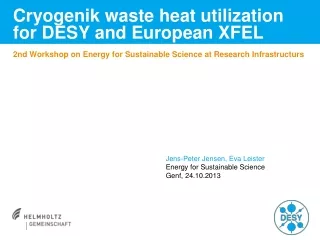
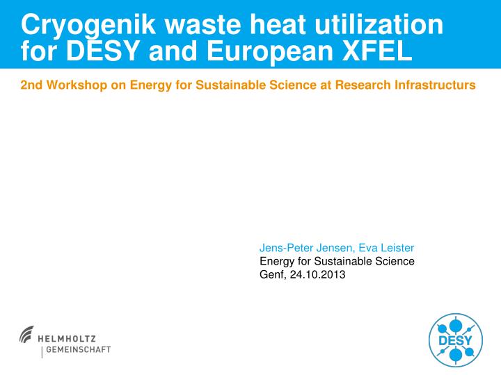
Cryogenik waste heat utilization for DESY and European XFEL. 2nd Workshop on Energy for Sustainable Science at Research Infrastructurs. Jens-Peter Jensen, Eva Leister Energy for Sustainable Science Genf, 24.10.2013. DESY campus. DESY premises heat distribution.

E N D
Cryogenik waste heat utilization for DESY and European XFEL 2nd Workshop on Energy for Sustainable Science at Research Infrastructurs Jens-Peter Jensen, Eva Leister Energy for Sustainable Science Genf, 24.10.2013
DESY premises heat distribution Heat distribution pipes 110 °C (red) Heat pipes 80 °C (blue) XFEL cryogenics plant XFEL injector district heating transfer station
Energy foot print of DESY and XFEL DESY premises in 2015 ff • Electrical energy: 160 GWh, 25 MW • Heating energy: 20 GWh, 10 MW • Dominated by the accelerators and experimental halls XFEL operation at 10 Hz in 2016 ff • Electrical energy: 120 GWh, 20 MW • Heating energy: 10 GWh, 5 MW Schenefeld premises • Cryogenics electrical energy at 10 Hz: 24 GWh/a • Heating demand is predominant on the Schenefeld and Osdorf premises • XFEL cryogenic plant is on the DESY premises, ex HERA cryogenics plant • XFEL cryogenics waste heat utilization possible for DESY premises
Cryogenic Plant Functionality 300 K 6 K XFEL modules tunnel injector oil seperator compressors Subcooler 50°C 75°C Coldbox Dewar 40°C air cooler heat exchanger He preheater The helium-heater is only used when the subcooler is cooling down or heating up. Helium to the heat distribution return pipe Oil Breox B35 Oil-Helium mixture
Oilsystem of the XFEL Cryogenic Plant low pressure compressors heat exchanger for cryogenics waste heat utilization air/oil cooler
Temperature Plot of the Breox Oil in 2012 average: 70,2 °C oil temperature of the high pressure compressor in 2012
Heat emission of 1 street of the cryogenic plant in 2012 average value: 823 kW
Heat Distribution Sceme of DESY Premises UST 28c UST 67-1 UST FLASHII UST 47 19 20 20a 38 UST CFEL UST Nanolab UST 49 UST 67-2 21 18 46 37 UST 72 22 UST PXN UST ZOQ 28 UST 67 UST 25b3 36 45 17 26 25 24 UST 25 27 UST 69 23 UST 8 41 42 UST 54 31 29 access to heat distribution UST 30 UST 24 UST 48 32 exist 16 15 XFEL cryogenic UST 25c 35 4a UST 62 30 40 UST CSSB cuts for calculations 14 UST 1d 33 39 34 UST 16 UST 2 UST 1a 4 5 UST 10 UST 64 7 44 13 UST 17 8 District heating transfer station 3 3a 9 12 UST 11a 1 10 2 UST = heat substation UST 5 UST 3b UST 80b 11 UST 7 6 UST 3 Vattenfall district heat supply
Simulation Models for MATLAB/Simulink district heat transfer station heat substation heat pipes heat exchanger of the cryogenic plant
Classified Heat Load Curve of 2012 DESY heat consumption 2012 20,9 GWh/a 1 street of the cryogenic plant 2 streets of the cryogenic plant
Results of Cryogenic Heat Utilization • price for district heat: 0,05 €/kWh • investment costs: 592 k€ • refunding rate: 10 % • district heat: 238 g CO2/kWh
Waste Heat Utilization from the XFEL Water Cooling Pump House Schenefeld Pump House DESY campus
Water Cooling of XFEL Injector and Main Linac XTL Electronic rack cooling in winter cooling towers compression chiller winter Tair<16°C summer Tair >16°C 25°C 40°C heatexchanger 28°C 18°C heatexchanger heatexchanger 20°C 30°C 20°C 30°C 30°C 14°C 8°C 45°C klystrons: 7500 kW magnets: 500 kW electronic racks: 200 kW (water cooled) air conditioning: 800 kW
Heat Distribution Sceme of DESY Premises UST 28c UST 67-1 UST FLASHII UST 47 19 20 20a 38 UST CFEL UST Nanolab UST 49 UST 67-2 21 18 46 37 UST 72 22 UST PXN UST ZOQ 28 UST 67 UST 25b3 36 45 17 26 25 24 UST 25 27 UST 69 23 UST 8 41 42 UST 54 31 29 UST 30 UST 24 UST 48 32 16 XHMP waste heat pump 15 UST 25c 35 4a UST 62 30 40 UST CSSB cuts for calculations 14 UST 1d 33 39 34 UST 16 UST 2 UST 1a 4 5 UST 10 UST 64 7 44 13 UST 17 8 District heating transfer station 3 3a 9 12 UST 11a 1 10 2 UST = heat substation UST 5 UST 3b UST 80b 11 UST 7 6 UST 3 Vattenfall district heat supply
Waste Heat Pump Calculation • Heat pump: 630 kW, Tcond = 85 °C, Tvap = 40 °C • Heat is transferred into the heat distribution return pipe • Investment costs are 725 k€ • Without heat utilization from the cryogenics • price for district heating: 0,05 €/kWh electricity: 0,15 €/kWh • investment costs: 725.000 € • adequate target rate: 10 % • district heating: 238 g-CO2/kWh elecricity: 336 g-CO2/kWh
Conclusion Cooling water waste heat utilization with heat pump • The most waste heat goes into the cooling water • The cooling water temperatures are to low for direct transfer into the heat distribution pipes • One needs a heat pump to boost the temperature • The savings does not pay back the invest and service costs and • The XFEL pump house XHMP is near the cryogenics hall • The heat pump is in competition with the cryogenics • This makes it even more uneconomic
Conclusion XFEL Cryogenic oil waste heat utilization The utilization of the oil waste heat pays back after 2 – 3 years Heat pump utilization to boost low temperatures does not pay