Download
1 / 34
340 likes | 497 Vues
Pipelined Control Chapter 6. Vishwani D. Agrawal James J. Danaher Professor Department of Electrical and Computer Engineering Auburn University http://www.eng.auburn.edu/~vagrawal vagrawal@eng.auburn.edu. Pipelined Datapath (without Jump). IF/ID. ID/EX. EX/MEM. MEM/WB. 4. 1 mux 0.

E N D
Pipelined ControlChapter 6 Vishwani D. Agrawal James J. Danaher Professor Department of Electrical and Computer Engineering Auburn University http://www.eng.auburn.edu/~vagrawal vagrawal@eng.auburn.edu ELEC 5200-001/6200-001 Lecture 13
Pipelined Datapath (without Jump) IF/ID ID/EX EX/MEM MEM/WB 4 1 mux 0 Add ALU opcode Shift left 2 26-31 zero 21-25 Instr mem ALU PC 16-20 Data mem. Reg. File 1 mux 0 0 mux 1 Sign ext. 16-20 for I-type lw 11-15 for R-type 1 mux 0 0-15 ELEC 5200-001/6200-001 Lecture 13
Mem. and Reg. File Need Controls IF/ID ID/EX EX/MEM MEM/WB 4 1 mux 0 Add ALU opcode Shift left 2 RegWrite 26-31 MemWrite MemRead zero 21-25 Instr mem ALU PC 16-20 Data mem. Reg. File 1 mux 0 0 mux 1 Sign ext. 16-20 for I-type lw 11-15 for R-type 1 mux 0 0-15 ELEC 5200-001/6200-001 Lecture 13
Multiplexers Need Controls IF/ID ID/EX EX/MEM MEM/WB 4 1 mux 0 Add ALU Shift left 2 opcode RegWrite PCSrc Branch 26-31 MemWrite MemRead MemtoReg zero ALUSrc 21-25 Instr mem ALU PC 16-20 Data mem. Reg. File 1 mux 0 0 mux 1 Sign ext. 16-20 for I-type lw 11-15 for R-type 1 mux 0 RegDst 0-15 ELEC 5200-001/6200-001 Lecture 13
ALU Needs a Control IF/ID ID/EX EX/MEM MEM/WB 4 1 mux 0 Add ALU Shift left 2 opcode RegWrite PCSrc Branch 26-31 MemWrite MemRead MemtoReg zero ALUSrc 21-25 Instr mem PC ALU 16-20 Data mem. Reg. File 1 mux 0 0 mux 1 ALU cont. Sign ext. 0-5 ALUOp 16-20 for I-type lw 11-15 for R-type 1 mux 0 RegDst 0-15 ELEC 5200-001/6200-001 Lecture 13
Compare with Single-Cycle Control • Control signals are the same as those needed for a single-cycle datapath. • Control signals are generated by the Opocode in the ID (instruction decode) cycle and then distributed to other cycles. • Let us reexamine the implementation of the single-cycle control (slides 3-8 of Lecture 10). ELEC 5200-001/6200-001 Lecture 13
Hardwired CU: Single-Cycle • Implemented by combinational logic. Control logic Datapath 6 funct. code Control signals To ALU 6 opcode 3 ALU control ALUOp 2 ELEC 5200-001/6200-001 Lecture 13
Jump 0-25 Shift left2 0 mux 1 4 Add 1 mux 0 ALU Branch opcode MemtoReg CONTROL 26-31 RegWrite ALUSrc 21-25 zero MemWrite MemRead ALU Instr. mem. PC Reg. File Data mem. 1 mux 0 16-20 0 mux 1 1 mux 0 11-15 Single-cycle Datapath RegDst ALUOp ALU Cont. Sign ext. Shift left 2 0-15 0-5 ELEC 5200-001/6200-001 Lecture 13
Single-Cycle Control Logic Op5 Op4 Op3 Op2 Op1 Op0 ALUOp1 MemtoReg MemRead ALUOp0 MemWrite RegWrite Jump Branch RegDst ALUSrc ELEC 5200-001/6200-001 Lecture 13
Single-Cycle Control Circuit Op5 Op4 Op3 Op2 Op1 Op0 lw R sw beq J RegDst ALUSrc MemtoReg RegWrite MemRead MemWrite Branch ALUOp1 ALUOp0 Jump ELEC 5200-001/6200-001 Lecture 13
ALU Control Logic ELEC 5200-001/6200-001 Lecture 13
ALU Control Operation select from control From Control Circuit ALUOp1 ALUOp0 3 zero ALU result F3 F2 F1 F0 overflow Operation select ALU function 000 AND 001 OR 010 Add 110 Subtract 111 Set on less than ELEC 5200-001/6200-001 Lecture 13
Returning to Pipelined Control • Opcode input to control is supplied by the pipeline register IF/ID in the ID (instruction decode) cycle. • Nine control signals are generated in the ID cycle, but none is used. They are saved in the pipeline register ID/EX. • ALUSrc, RegDst and ALUOp (2 bits) are used in the EX (execute) cycle. Remaining 5 control signals are saved in the pipeline register EX/MEM. • Branch, MemWrite and MemRead are used in the MEM (memory access) cycle. Remaining 2 control signals are saved in the pipeline register MEM/WB. • MemtoReg and RegWrite are used in the WB (write back) cycle. • Pipelined control is shown without Jump. ELEC 5200-001/6200-001 Lecture 13
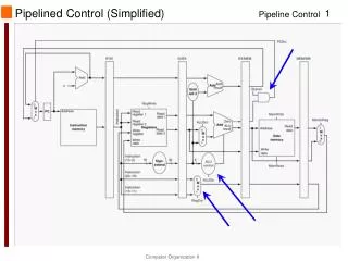
Placing Control in Pipelined Datapath IF/ID ID/EX EX/MEM MEM/WB 4 1 mux 0 Add ALU opcode Shift left 2 CONTROL 26-31 RegWrite PCSrc Branch MemWrite MemRead MemtoReg zero ALUSrc Instr mem 21-25 PC ALU 16-20 Data mem. Reg. File 1 mux 0 0 mux 1 ALU cont. Sign ext. ALUOp 0-5 16-20 for I-type lw 11-15 for R-type 1 mux 0 RegDst 0-15 ELEC 5200-001/6200-001 Lecture 13
Highlighted Pipelined Control IF/ID ID/EX EX/MEM MEM/WB 4 Add 1 mux 0 ALU opcode Shift left 2 CONTROL 26-31 RegWrite PCSrc Branch MemWrite MemRead MemtoReg zero ALUSrc Instr mem 21-25 PC ALU 16-20 Data mem Reg. File 1 mux 0 0 mux 1 ALU cont. Sign ext. ALUOp 0-5 16-20 for I-type lw 11-15 for R-type 1 mux 0 RegDst 0-15 ELEC 5200-001/6200-001 Lecture 13
Single-Cycle Performance • Assume • 200 ps for memory access • 100 ps for ALU operation • 50 ps for register file read or write • Cycle time set according to longest instruction: lw ≡ IF + ID/RegRead + ALU + MEM + RegWrite = 200 + 50 +100 + 200 + 50 = 600 ps • Instruction time = 600 ps ELEC 5200-001/6200-001 Lecture 13
Multicycle Performance • Consider SPECINT2000 instruction mix: • 25% lw 5 cycles • 10% sw 4 cycles • 11% branch 3 cycles • 2% jump 3 cycles • 52% ALU instr . 4 cycles • Av. CPI = 0.25×5 + 0.10×4 + 0.11×3 + 0.02×3 + 0.52×4 = 4.12 • Clock cycle time determined from longest operation (memory access) = 200 ps • Average instruction time = 4.12×200 = 824 ps ELEC 5200-001/6200-001 Lecture 13
Pipeline Performance • Neglect initial latency (ok for long programs). • One instruction completed every clock cycle unless delayed by hazard. Average CPI: • lw 2 cycles 50% times due to hazard 1.5 cycles • sw 1 cycle • ALU 1 cycle • branch 2 cycles 25% times due to hazard 1.25 cycles • jump 2 cycles • For SPECINT2000 Av. CPI = 0.25×1.5 + 0.10×1 + 0.11×1.25 + 0.02×2.0 + 0.52×1 = 1.17 • Clock cycle time from longest operation (memory access) = 200 ps • Average instruction time = 1.17×200 = 234 ps ELEC 5200-001/6200-001 Lecture 13
Comparing Alternatives ELEC 5200-001/6200-001 Lecture 13
Next • Forwarding • Stall • Branch hazard and branch prediction • Instruction flush • Exceptions ELEC 5200-001/6200-001 Lecture 13
MEM:DM MEM:DM IF: IM IF: IM EX: ALU EX: ALU WB: REG. WRITE WB: REG. WRITE ID: REG. FILE READ ID: REG. FILE READ EX/MEM EX/MEM IF/ID IF/ID ID/EX ID/EX MEM/WB MEM/WB Forwarding • Consider a data hazard: sub $2, $1, $3 # computes result in CC3, writes in $2 in CC5 and $12, $2, $5 # reads $2 in CC3, adds in CC4 CC1 CC2 CC3 CC4 CC5 CC6 CC7 CC8 CC3: sub saves new data in EX/MEM, to be written to $2 in CC5 sub $2, $1, $3 and $12, $2, $5 CC3: and reads $2 to ID/EX, but the correct data is in EX/MEM CC4: forwarding allows execution of and with correct data ELEC 5200-001/6200-001 Lecture 13
Understanding Forwarding • Let’s ask the following questions: • Q: Why is there a hazard? • A:Source register of present instruction is the same as the destination register of the previous instruction. • Q: When is the source register data needed? • A: In the execute cycle (CC4). • Q: Issource register data available in CC4? • A: Yes – use forwarding. No – use stall. • Q: Where is the required data in CC4? • A: In the pipeline register EX/MEM as ALU output. ELEC 5200-001/6200-001 Lecture 13
Forwarding Hardware • A forwarding unit is added to execute (ALU) hardware. • Functions of forwarding unit: • Hazard detection • Forward correct data to ALU • Inputs to forwarding unit: • Source registers of present instruction • Destination registers of previous instructions • Outputs of forwarding unit: multiplexer controls to route correct data to the ALU. ELEC 5200-001/6200-001 Lecture 13
Recall Register Definitions • R-type instruction (add, sub, and, or, . . . ) opcode Rs Rt Rd shamt funct • I-type instruction (beq, lw, sw, addi, . . . ) opcode Rs Rt constant_or_address • J-type instruction (j, jal, jr) opcode a___d___d___r___e___s___s • Where • Rs is the first source register • Rt is the second source register • Rd is the destination register ELEC 5200-001/6200-001 Lecture 13
Forwarding Implemented ID/EX EX/MEM MEM/WB IF/ID Branch addr. PC+4 ALU opcode Shift left 2 26-31 Addr mem 21-25 zero MUX 16-20 Reg. File ALU Data mem. 1 mux 0 0 mux 1 MUX Sign ext. 16-20 11-15 1 mux 0 Rd Rs 21-25 Forwarding unit 16-20 Rt Rd 0-15 ELEC 5200-001/6200-001 Lecture 13
DM DM IM IM ID, REG. FILE READ ID, REG. FILE READ ALU ALU REG. FILE WRITE REG. FILE WRITE MEM/WB MEM/WB IF/ID IF/ID ID/EX ID/EX EX/MEM EX/MEM Stall • Delay next instruction by sending noop through pipeline. • Necessary when hazard not resolved by forwarding. CC1 CC2 CC3 CC4 CC5 CC6 CC4: new data in MEM/WB, to be written to $2 lw $2, 20($1) and $4, $2, $5 CC4: execution of and is impossible; correct data unavailable until end of CC4 ELEC 5200-001/6200-001 Lecture 13
Detecting Hazard Requiring Stall • Consider instruction in IF/ID being decoded: • If • Previous instruction activated MemRead, and • Instruction being decoded has a source register (Rs or Rt) same as the destination register (Rt for lw) of the previous instruction • Then, stall the pipeline: • Force all control outputs to 0 • Prevent PC from changing • Prevent IF/ID from changing ELEC 5200-001/6200-001 Lecture 13
Stall Implementation Rt MemRead Hazard detection unit PCWrite IF/IDWrite Rs ID/EX EX/MEM MEM/WB opcode IF/ID Control 26-31 MUX 0 Shift left 2 21-25 zero MUX PC Addr mem Reg. File 16-20 ALU 1 mux 0 Data mem. 0 mux 1 MUX Sign ext. 16-20 11-15 1 mux 0 Rd Rs 21-25 Forwarding unit 16-20 Rt Rd 0-15 ELEC 5200-001/6200-001 Lecture 13
MEM:DM EX: ALU WB: REG. WRITE ID: REG. FILE READ EX/MEM IF/ID ID/EX MEM/WB MEM:DM MEM:DM MEM:DM IF: IM IF: IM IF: IM EX: ALU EX: ALU EX: ALU WB: REG. WRITE WB: REG. WRITE WB: REG. WRITE ID: REG. FILE READ ID: REG. FILE READ ID: REG. FILE READ EX/MEM EX/MEM EX/MEM IF/ID IF/ID IF/ID ID/EX ID/EX ID/EX MEM/WB MEM/WB MEM/WB Stall • Execution with stall and forwarding: CC1 CC2 CC3 CC4 CC5 CC6 CC7 CC4: new data in MEM/WB, to be written to $2 lw $2, 20($1) bubble (nop) and $4, $2, $5 State of IF/ID is frozen in CC3 next is fetched twice since PC was frozen IF: IM IF/ID next ELEC 5200-001/6200-001 Lecture 13
Branch Hazard • Consider heuristic – branch not taken. • Continue fetching instructions in sequence following the branch instructions. • If branch is taken (indicated by zero output of ALU): • Control generates branch signal in ID cycle. • branch activates PCSource signal in the MEM cycle to change PC with the branch address. • Three instructions in the pipeline must be flushed. ELEC 5200-001/6200-001 Lecture 13
Branch Hazard IF/ID ID/EX EX/MEM MEM/WB 4 1 mux 0 Add ALU opcode Shift left 2 CONTROL 26-31 RegWrite PCSrc Branch MemWrite MemRead MemtoReg beq ALUSrc zero Instr mem 21-25 PC ALU 16-20 Data mem. Reg. File 1 mux 0 0 mux 1 ALU cont. Sign ext. ALUOp 0-5 16-20 for I-type lw 11-15 for R-type 1 mux 0 RegDst 0-15 ELEC 5200-001/6200-001 Lecture 13
Pipeline Flush • If branch is taken (as indicated by zero), then control does the following: • Change all control signals to 0, similar to the case of stall for data hazard, i.e., insert bubble in the pipeline. • Generate a signal IF.Flush that changes the instruction in the pipeline register IF/ID to 0 (nop). • Penalty of branch hazard is reduced by • Adding branch detection and address generation hardware in the decode cycle. • Using complex (static or dynamic) branch prediction. ELEC 5200-001/6200-001 Lecture 13
Branch Prediction • Useful for program loops. • Uses a two-bit state machine Not taken Predict branch taken 00 Predict branch taken 01 taken taken Not taken taken Not taken Predict branch not taken 10 Predict branch not taken 11 Not taken taken ELEC 5200-001/6200-001 Lecture 13
Exceptions • A typical exception occurs when ALU produces the overflow signal. • Control asserts following actions on exception: • Change the PC address to 4000 0040hex. This is the location of the exception routine. This is done by adding an additional input to the PC input multiplexer. • Overflow is detected in the EX cycle. Similar to data hazard and pipeline flush, • Set IF/ID to 0 (nop). • Generate ID.Flush and EX.Flush signals to set all control signals to 0 in ID/EX and EX/MEM registers. This also prevents the writing of the ALU result (presumed contaminated) from being written in the WB cycle. ELEC 5200-001/6200-001 Lecture 13