Download
1 / 21
210 likes | 341 Vues
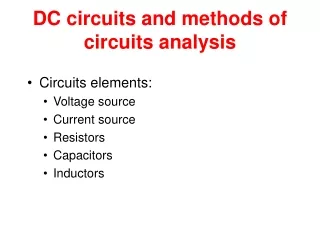
Methods of Analyzing the Networks (DC). Lecture No.6 By – Engr Sajid Hussain Qazi MUET S.Z.A Bhutto Campus Khairpur. Methods of analysis allow us to approach, in a systematic manner , a network with any number of sources in any arrangement.

E N D
Methods of Analyzing the Networks (DC) Lecture No.6 By – EngrSajidHussainQazi MUET S.Z.A Bhutto Campus Khairpur
Methods of analysis allow us to approach, in a systematic manner, a network with any number of sources in any arrangement. These methods can also be applied to networks with only one source. The methods to be discussed in detail in this lecture include: -Branch-current analysis (Loop Analysis), -Mesh analysis, and -Nodal analysis. All the methods can be applied to Linear Bilateral Networks. The term linear indicates that the characteristics of the network elements (such as the resistors) are independent of the voltage across or current through them. The second term, bilateral, refers to the fact that there is no change in the behavior or characteristics of an element if the current through or voltage across the element is reversed. Engr. S.H.Qazi
Branch Current Analysis ( Loop Analysis ) Method To analyze the network using Loop analysis method, then we have to follow the list of steps required for its application. There are four steps, as indicated below. 1. Assign a distinct current of arbitrary direction to each branch of the network. 2. Indicate the polarities for each resistor as determined by the assumed current direction. 3. Apply Kirchhoff’s voltage law around each closed loop in clockwise direction. Way to determine how many times KVL will have to be applied is to determine number of closed loops in the network. Here fig-1 has two closed loops and fig-2 has three closed loops. Engr. S.H.Qazi 1 1 2 2 3 Fig-1 Fig-2 Determining the number of independent closed loops.
4.Apply Kirchhoff’s current law at the minimum number of nodes Total numbers of nodes less than one node will define how many times KCL will have to be applied on the network to find the current in the branches. Engr. S.H.Qazi Solve the resulting simultaneous linear equations for assumed branch currents.
Example-1 Apply the branch-current method (Loop Analysis) to the network of figure shown. Step 1: Since there are three branches (cda, cba, ca), three currents of arbitrary directions (I1, I2, I3) are chosen, as indicated in Fig-1. The current directions for I1 and I2 were chosen to match the voltage applied by sources E1 and E2, respectively. Since both I1 and I2 enter node a, I3 is leaving. Fig-1 Step 2: Polarities for each resistor are drawn to agree with assumed current directions, as indicated in Fig-2. Engr. S.H.Qazi Fig-2
Step 3: Since there are two closed loops so, Kirchhoff’s voltage law is applied around each closed loop (1 and 2) in the clockwise direction: Engr. S.H.Qazi
Step 4: Applying Kirchhoff’s current law at node a (in a two-node network, the law is applied at only one node). Since there are three equations and three unknowns Engr. S.H.Qazi Put eq—(3) in eq—(1 and 2)
Simultaneously solve both equations We get, Put value of I1 in eq—(a) Engr. S.H.Qazi Put value of I1 and I2 in eq—(3)
Example-2 Apply the branch-current method (Loop Analysis) to the network of figure shown. Apply KCL at node ‘a’ Engr. S.H.Qazi Substitute value of I2 in second equation..
Simultaneously solve equations (1 and 3) Put value of in equation (1) Engr. S.H.Qazi Put value of I1 and I3 in equation (3)
Mesh Analysis Method The second method of analyzing the network is to be described as mesh analysis. In mesh analysis method there is no need to use KCL. The systematic approach outlined below should be followed when applying this method. 1. Assign a distinct current of arbitrary direction to each branch of the network. 2. Indicate the polarities for each resistor as determined by the assumed current direction. 3. Apply Kirchhoff’s voltage law around each closed loop in clockwise direction. Engr. S.H.Qazi Solve the resulting simultaneous linear equations for the assumed loop currents.
Consider the same basic network as in Example 1 of the preceding section, now appearing in Fig-1. Step 1: Two loop currents (I1 and I2) are assigned in the clockwise direction Step 2: Polarities for each resistor are drawn to agree with assumed current directions. Step 3: Since Kirchhoff’s voltage law is applied around each closed loop (1 and 2) in the clockwise direction: Engr. S.H.Qazi
Re-writing both equation of loop 1 and 2, we get Simultaneously solving equations of loop 1 and 2 The minus signs indicate that the currents have a direction opposite to that indicated by the assumed loop current. Engr. S.H.Qazi The actual current through the 2-V source and 2- resistor is therefore 1 A in the other direction, and the current through the 6-V source and 1- resistor is 2 A in the opposite direction indicated on the circuit. The current through the 4- resistor is determined by the following equation from the original network:
Example- Apply the Mesh Analysis to the network of figure shown to find current through each branch. Engr. S.H.Qazi
Super Mesh Current On occasion there will be current sources in the network to which mesh analysis is to be applied. In such case we remove current source with equivalent open circuit and then apply KVL on the remaining independent paths of the network. The example will clarify the definition of a super mesh current and the procedure Example- Apply the Mesh Analysis to the network of figure shown to find current. Engr. S.H.Qazi Engr. S.H.Qazi
First, the mesh currents for the network are defined, as shown in Fig. Then the current source is removed, as shown in Fig. Engr. S.H.Qazi
Kirchhoff’s voltage law is applied to the resulting network. At node a Resulting two equations and two unknowns Simultaneously solve both equations, we get Engr. S.H.Qazi
Nodal Analysis Method • In loop analysis method the general network equations were obtained by applying Kirchhoff’s voltage law around each closed loop. We will now employ Kirchhoff’s current law to develop a method referred to as nodal analysis. • A node is defined as a junction of two or more branches. • For a network of N nodes, therefore, there will exist (N-1) nodes with a fixed potential relative to the assigned reference node. • Equations relating these nodal voltages can be written by applying Kirchhoff’s current law at each of the (N-1) nodes. • To obtain the complete solution of a network, these nodal voltages are then evaluated in the same manner in which loop currents were found in loop analysis. Engr. S.H.Qazi
The nodal analysis method is applied as follows: 1. Determine the number of nodes within the network. 2. Pick a reference node, and label each remaining node with a subscripted value of voltage as V1, V2, and so on. 3. Apply Kirchhoff’s current law at each node except the reference. 4. Solve the resulting equations for the nodal voltages. EXAMPLE - Apply nodal analysis to the network of Fig. shown Steps 1 and 2: The network has two nodes, as shown in Fig. The lower node is defined as the reference node at ground potential (zero volts), and the other node as V1, the voltage from node 1 to ground.
Step 3: I1 and I2 are defined as leaving the node in Fig. and Kirchhoff’s current law is applied as follows: The current I2 is related to the nodal voltage V1 by Ohm’s law: The current I1 is also determined by Ohm’s law as follows: Engr. S.H.Qazi Substituting into the Kirchhoff’s current law equation: Re-arranging the equation, we get
Substituting numerical values, we get The currents I1 and I2 can then be determined using the preceding equations: The minus sign indicates simply that the current I1 has a direction opposite to that appearing in Fig. above Engr. S.H.Qazi