Download
1 / 40
400 likes | 564 Vues
The High power proton accelerator for the European Spallation Source (ESS ). S. Gammino. Milano, 9 Marzo 2012. Present Geometry and Top-Level Parameters. Energy 2.5 GeV Current 50 mA Average power 5 MW Pulse length 2.86 ms (new value since April 2011, equal to 2×20/14)

E N D
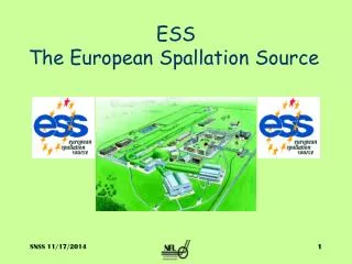
The High power proton accelerator for the European Spallation Source (ESS) S. Gammino Milano, 9 Marzo 2012
Present Geometry and Top-Level Parameters Energy 2.5 GeV Current 50 mA Averagepower 5 MW Pulselength 2.86 ms (new valuesince April 2011, equalto 2×20/14) Rep rate 14 Hz (new valuesince April 2011) Length 482 m, plus HEBT Max cavity field 40 MV/m Reliability > 95% Longerthanpreviouslybecauseof ”hybrid design”, smoother longitudinal phaseadvance, lowerfield gradients, ...
ACCELERATORS • High power, highly reliable Front Ends • High intensity light ions Linacs : systems design, beam dynamics, performance and current projects, reliability issues, • Synergies with ongoing and planned projects on accelerator driven systems, transmutation, neutrino factories, HEP injectors, materials science • Beam loss handling and diagnostics systems for high brightness hadron accelerators (≪1 W/m with localized exceptions) • Current state of theory and simulation tools, confronting predictions with experiment, • Low-energy superconducting structures, to be checked: how competitive they are for energies below 100 MeV…
ACCELERATORS • Radio frequency issues: where are we on high-gradient cavities and high power couplers, and current expectancies; current problems with the operation of high power, high duty cycle klystron/modulator systems, • Compatibility of the proposed ESS design with future upgrades • Energy usage, how to minimize electricity consumption without seriously compromising the performance
Parameters for the ESS linac In comparison to the originally proposed design (5 MW, 1 GeV, 150 mA) the parameters have been modified in 2009 in order to simplify the linac design and to increase its reliability. The current has been decreased and the final energy increased, keeping the footprint of the accelerator the same. • Decrease in current – With increased energy the average pulse current is reduced • Increase of the cavity gradient – By decreasing the current, the gradient can be raised to 15 MV/m, keeping the coupler power constant. • Increase of beam energy. • Repetition rate - The originally proposed repetition rate of 16.67 Hz has been changed to 20 and then to 14 Hz. • Pulse length –2.86 ms
Cavities and Cryomodules • Power Couplers • Transition Energy from Warm to Cold Sections • Higher Order Modes • Cryomodules • Cryogenics The linacparameters that were used are consistent with the SRF technology available today or that is expected to be in a 2 year period. No fundamental issue was identified. However there is still a large amount of work that remains to be done towards the engineering various components. High-power RF architecture • 1 klystron per cavity • 1 klystron to power several cavities
Main topics addressed: modelling codes, radiation issues, longitudinal and transverse measuring techniques Main message: more diagnostic equipment than envisaged • Beam Diagnostics • Linac Front-Ends • Beam Dynamics Beam Diagnostics • The primary linac diagnostic needs include beam position, beam arrival time (or phase), beam bunch length, beam transverse profiles, and beam loss. • Especially important for high power operation are sensitive beam loss measurement and profile resolution over a wide dynamic range. • Techniques for halo measurement in a superconducting environment need to be developed.
AcceleratorClear elements: main requirements, items that deserve additional R&D.“Obscure” elements: transition elements between different sections, partnership definition complicated by the workloads of involved research teams.Strength points: for most of the components (e.g. Front-End until the warm-cold transition, elliptical cavities) there is a sufficient/remarkable experience within the Institutions involved in ESS.INFN is recognized to own a remarkable expertise in the design of HPPA accelerators.Italian contribution to the Accelerator DU: Ion Source, LEBT, DTL, elliptical cavities, know-how about RFQ and superconductivity useful know-how for ESS design and construction.
Collaboration model for linacdesign update (ADU) Work Packages 1. Management Coordination – ESS (Mats Lindroos) 2. Accelerator Science – ESS (Steve Peggs) 3. Infrastructure Services – Tekniker, Bilbao, now ESS Lund 4. SCRF Spoke cavities – IPN, Orsay (SebastienBousson) 5. SCRF Elliptical cavities – CEA, IRFU-Saclay (Guillaume Devanz) with contribution by INFN 6. Front End and NC linac – INFN(Santo Gammino) 7. Beam transport, NC magnets and Power Supplies – Århus University (SørenPape-Møller) 8. RF Systems – ESS (Dave Mc.Ginnis) 19. Test stand – Uppsala university (Roger Ruber)
ADU Project Plan 900 tasks/milestones, 294 deliverables 189 968 hours
WP 8 and WP 19 • The complexity of the RF system, the high cost and the close integration needs with the conventional facilities has made it necessary to move WP 8 (RF systems) to Lund. • New planning has been submitted and EPG have decided to appoint David McGinnis as WP leader • Uppsala is proposed to lead a new WP 19 on Test stands. The WP is a P2B WP and we propose to launch it ASAP to avoid any issues with the UU contract. • The addenda will have the same total budget as the present UU WP • The new WP at UU: Uppsala will build a test stand with a complete 352 MHz RF source including the low level RF system which is designed and built at LU • Test of complete RF system • Test of LLRF (control of phase, frequency and amplitude) with test cavity from Orsay • System test of RF system and test at full power of complete spoke cavity Cryo Module from Orsay • Test of recombination of RF sources for future upgrades • Survey of existing European test stands for ESS construction phase
Comments from TAC-4 (Feb.16th,2012) • Good progress with ADU project… • …goal is to have requirement specifications, interface control documents, cost and schedule for construction for the end of 2012 (together with TDR) • Responsibilities and organization adapted to new situation with project office at ESS and a stronger accelerator division at ESS • Evolving baseline and the CDR is a snapshot of the status in November 2011 • However, baseline is converging – many decisions taken since last TAC! 14
ESS Project Strategy • P2B • assures a stringent project framework for prototyping the design choices in the technical design • a continuous transition from design to construction and keeps the collaborations intact through the construction decision process P2B projects Construction projects Design Updates International convention signed First neutrons TDRs with cost and Schedule Cryomodule production starts First protons Const. Const. P2B P2B P2B DU DU 16 P2B
Project plan for the linac design update and prototyping • Design Report for the end of 2012, 20% precision in costing • Readiness to construct by the end of 2012 -- the design will be a safe baseline design with technical choices made for which the writing of specifications, detailed drawings and completion of late prototypes could be launched without any further delay after 2012 • Energy budget and sustainability should be taken into account in each work package
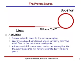
The high current proton source will be based on the know-how acquired during the design phase and the construction phase and commissioning of the sources named TRIPS and VIS at INFN-LNS and of the SILHI source at CEA-Saclay. TRASCO INTENSE PROTON SOURCE (TRIPS) Beamenergy 80 keV Current up to 60 mA Proton fraction > 80% RF power < 1 kW @ 2.45 GHz CW mode Reliability 99.8% over 142 h (35 mA) Emittance 0.07 π mm mrad (32 mA), 0.15 to 0.25 atmaxcurrent Test benches available at INFN-LNS and at CEA-IRFU
Proton source & Tests SILHI 90mA f=9mm VIS-Versatile IonSource
RFQ ANALYSIS sensitivity to dipole-like perturbations: the RFQ can be made naturally stable with proper choice of vane undercuts: 23 mm at RFQ input, 25 mm at RFQ output. sensitivity to quadrupole-like perturbations: RFQ ends are tuned with adjustable-length rods. quadrupole mode closer to accelerating mode Q0 is Q1: 1.47 MHz frequency shift, +31.9 MHz quadratic frequency shift dipole modes closer to accelerating mode Q0 are D2 : -5.5 MHz shift, -61.3 MHz QFS D3 : +2.3 MHz shift, +40.3 MHz QFS
Research Programs in Europe related to ADS studies IPHI@Saclay.CEA TRASCO@LegnaroINFN
MEBT Room for diagnostics & Vacuum elements
Drift tube Linac As for this part, INFN-LNL team has already designed an accelerator with similar performances and has prototyped with Italian industry, together with CERN Linac4 team, a common prototype tank approximately 1 m long (prototype for Linac4 and SPES driver). The collaboration with CERN team could continue and the DTL may be built on the basis of this R&D. If we look in details to the different parameters of the Linac4 and ESS DTL, there is an evident similarity concerning pulse current, gradient, injection energy, and some difference exists for output energy and duty cycle only. For this reason, there is no need of prototyping for NC Linac, but a careful analysis of the optimum design, adapted to the ESS parameters, is under way, to put in evidence possible criticalities and maximize the reliability .
Analisys of RF Stem Effect on fields shape Stem volume that perturbs first cell is less than that which perturbs second one. We decrease triangle height until cell resonant frequency is less than that corrected for stem (moving A point from top to bottom); we decrease triangle base until cell resonant frequency is equal to that corrected for stem (moving B point from left to right).
CERN-INFN DTL prototype, based on CERN design Tank machining at Cinel (Vigonza-Italy)
Disadvantages Matching, cost, length (notcompensated by cryogenics’ savings
First prototype in 2013 at IPN-Orsay
Ellipticalcavities design at CEA-IRFU, Saclay The ellipticalsuperconductinglinacconsists of twotypes of cavities – medium beta and high beta – to accelerate the beam from the spokesuperconductinglinacenergy (191 MeV) up to full energy (653 MeV in the medium beta, 2500 MeV the high beta). The profile of a 5-cell high beta cavityisshown in Figure.
Perspectives • A clearpathtowards the definition of each component of the acceleratoristracked. • Reliability issues and possibility to upgrade havedriven the efforts of ADU WPs. • Some open questions are still on the table with the aim to reduce costs and increasebeamavailability. • Team building iswellplaced. • Links betweenaccelerator’s designers and infrastructure are established. • Second half 2012: TDR and costing • Ready to build ESS since 2013!