Download
1 / 24
260 likes | 912 Vues
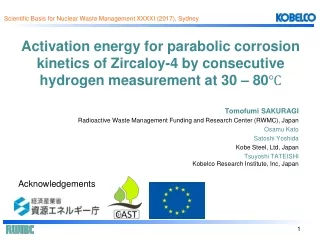
Synthesis and microstructural characteristics of simulated iodine-bearing waste formed by HIP sintering of the silver impregnated alumina sorbent. Tomofumi SAKURAGI Radioactive Waste Management Funding and Research Center (RWMC), Japan Satoshi Yoshida Osamu Kato Kobe Steel, Ltd, Japan

E N D
Synthesis and microstructural characteristics of simulated iodine-bearing wasteformed by HIP sintering of the silver impregnated alumina sorbent Tomofumi SAKURAGI Radioactive Waste Management Funding and Research Center (RWMC), Japan Satoshi Yoshida Osamu Kato Kobe Steel, Ltd, Japan Kaoru MASUDAKobelco Research Institute, Inc, Japan 12th International Conference on Hot Isostatic Pressing, Sydney
Radioactive Waste in Japan • Waste classification and disposal concept • Surface Disposal for LLW; Operated by JNFL at Rokkasho-mura • Intermediate depth disposal for ILW; Conducted full scale site survey at Rokkasho • Geological Disposal for HLW & TRU wastes; Started the site selection process Intermediate depth disposal
Commercial Reprocessing Plant in Japan (Rokkasho) • Capacity • 800 tons-U/year reprocessing • In 40 years operation, total 32,000 tU will be reprocessed • Progress of the plant • 1993 Starts constructing • 2002 Chemical (cold) test, 2004 Uranium test, 2006 Active (hot) test, 425 tU, (4 t-Pu recovered, 346 HLW produced) • After the Fukushima accident in 2011, Applying for conformance with the New Regulatory Requirements • Scheduled completion in 2018 (must be postponed again) • Full operation will start within a few years • Radioactive wastes • High level waste (HLW); 40,000 canisters • TRU waste; 100,000 m3 From JapanNuclearFuelLimited (JNFL, Rokkasho)
TRU Waste in Japan • TRU waste is defined as waste containing long-lived radionuclides generated from reprocessing plants, except HLW. • TRU waste is categorized into 4 groups. • The spent silver-absorbent (iodine filter) is categorized as Group 1 for deep geological disposal. *FEPC and JAEA: Second Progress Report on Research and Development for TRU Waste Disposal in Japan (2007) Grouping of TRU waste for deep geological disposal*
Iodine Waste • Spent silver sorbent (iodine filter, Gr.1) • The Japanese commercial reprocessing plant in Rokkasho is equipped with an advanced system that prevents the release of volatile iodine into the outside environment, which is probably the only one in the world. • Iodine is released forcibly in the dissolving process to off-gas system and is collected by an iodine filter (silver sorbent) . • The spent silver sorbents are projected to be 150 tons for 40 years operation. Receiving/Storage Shearing/Dissolving Separation Purification Denitration Product storage 129I Shearing U purification Cask FP separation U,Pu separation Uranium oxide Pool Dissolving Spent fuels Pu purification Metal chips, etc. High lever liquid U/Pu mixed oxide (MOX) Stored into canisters Vitrification Claddings etc. Pu U Fission Products
Iodine Sorbent (Silver sorbent, AgA) • Fundamental features • Alumina, a base material • Silver nitrate is deposited on the alumina surface • Iodine adsorbs as a AgI (Alumina)-AgNO3 + I2 (CH3I) → (A)-AgI + NOx Size 1-3 mm Iodine adsorbed (Simulated spent sorbent) Virgin silver sorbent EPMA
Iodine 129 • Properties in safety case (disposal safety) • Half life; 15,700,000years • Inventory; 5.1×10¹³ Bq (150 tons of spent sorbent) • Anion species in ground water (Mobile nuclides) • Large impact on the exposure dose for a long term disposal safety (400 times larger dose than HLW) Gr.1 Gr.2 FEPC and JAEA, 2nd Progress Report on Research and Development for TRU Waste Disposal in Japan (2007).
Iodine-bearing Waste Form • Candidate immobilization techniques* • Ceramic • Alumina matrix (Present work) • Apatite • Sodalite • Glass • Phosphate AgI glass • BPI glass • Cement • IO3-cement • Metallic *B.J. Riley et al., J. Nucl. Mater. 470, 307-326 (2016). *K. Idemitsu, Mater. Res. Soc. Symp. Proc. 1744, 3-13(2015). BPI glass: Low temperature vitrification of lead borate glass Iodine Lead Boron Oxygen Mukunoki et al., Microscopic Structural Analysis of Lead Borate-Based Glass, Progress in Nuclear Energy 91, 339-344 (2016). IO3-cement : Gypsum additive calcium aluminate cement, enriched with ettringite (AFt) Sakuragi et al., Effect of hydration heat on iodine distribution in gypsum-additive calcium aluminate cement, Ceramic Transactions 260, 185 (2015). Yamashita et al., Iodine Release Behavior from Iodine-Immobilized Cement Solid under Geological Disposal Conditions, Progress in Nuclear Energy 92 , 273–278 (2016).
Alumina Matrix Solid • Overview (consolidation process) • A simple process that does not isolate the adsorbed iodine from spent silver sorbent (AgA). • The base material of primarily waste (AgA, alumina) can be used as a solidification matrix (corundum). • Iodine is physical confinement as a AgI in the corundum matrix. Iodine adsorbed (Simulated spent sorbent) Size 1-3 mm Powdered Size <40 μm HIPing 175 MPa 1200oC 3 hours Pre-treatmentbyheating to remove gas components (NOx)
Dr. HIP • Specification (by KOBE Steel, LTD) • Graphite heater • Pressure Medium; Ar • Pressure vessel (Φ50mm×75mmL) • MAX Temperature; 2000oC • MAX Pressure; 196 MPa (2000 kgf/cm2) • Size; 1255mm(W)×1100mm(D)×1300mm(H) • Weight; 870 kg Capsule Pressure vessel Graphite Heater
Development Progress of Alumina Matrix Solid • 1st step (Sakuragi et al., 2015) • Preparation and characteristics of simulated spent sorbent (AgA) • Simply HIPed by AgA • Porosity of the solid was 13% • 2nd step • Improved pre-treatment (strong vacuum-heating process) • Porosity less than 5% (Masuda et al., 2016) • AgI connected in the solid (Present work) • 3rd step (Present work) • Addition of alumina reagent with AgA • To reduce the connectivity of AgI • Porosity less than 5% T. Sakuragi et al., Effects of hydrosulfide and pH on iodine release from an alumina matrix solid confining silver iodide, Mater. Res. Soc. Symp. Proc. 1744, 21-28 (2015). K. Masuda et al., Iodine immobilization: Development of solidification process for spent silver-sorbent using hot isostatic press technique, Progress in Nuclear Energy 92, 267-272 (2016).
Simulated Spent Sorbent (AgA) • Preparation and features • Virgin AgA was obtained from a supplier of the reprocessing plant. • Simulated spent sorbent was prepared by a dry process passing through sublimated iodine in a heated column and adsorbed onto AgA. • EPMA of the cross section shows the silver and iodine • distribution . • XRD confirmed AgI in the simulated sorbent. • A part of alumina are amorphous. Corundum (α-Al2O3) θ, δ-Al2O3 AgI I Ag Ag I Size 1-3 mm Virgin silver sorbent XRD pattern for simulated spent sorbent Iodine adsorbed (Simulated spent sorbent)
1st Step • Process • Simple pretreatment; AgA was powdered and heated at 480oC for 3h. to remove NOx. • Packed in to HIPing capsule (100 mL size) and evacuated with a rotary pump. • HIPed under 1200oC, 175 MPa, 3h. • Product properties • Iodine loading is 10% (20% as AgI). • A part of iodine (IO3) might be volatilized during heat treatment and evacuation. • Alumina is well crystalized into corundum (a-alumina). • Simple composition of corundum and AgI. Spent sorbent Chemical composition (wt%) After HIPing
1st Step • Internal view of solid • AgI is surrounded by corundum particles. • Porous (13% porosity). • Iodine leaching behavior • Aqueous immersion tests in the presence of HS- ion. • HS- ion is a common and strong reducing agent in ground water. • 2AgI + HS- → Ag2S + 2I-(confirmed by XRD). • Iodine was easily leached due to the high porosity. Leaching tests Normalized elemental mass loss (MAX 6383) T. Sakuragi et al., Effects of hydrosulfide and pH on iodine release from an alumina matrix solid confining silver iodide, Mater. Res. Soc. Symp. Proc. 1744, 21-28 (2015).
2nd Step • Improved pretreatment* • Pre-heated at 480oC for 3h. • Strong vacuum-heating treatment (0.07 Pa, 400oC, 2h.) to remove completely the adsorbed water on AgA. • HIPed under 1200oC, 175 MPa, 3 h. • Product properties • Successful densification (porosity less than 5%). • Iodine leaching decreased, however, it was not as expected reduction. • 2AgI + HS- → Ag2S + 2I- Leaching tests Corundum Pore; less than 5% AgI SEM observation *Masuda et al., Iodine immobilization: Development of solidification process for spent silver-sorbent using hot isostatic press technique, Progress in Nuclear Energy 92, 267-272 (2016).
Internal Structure Model • High iodine leaching for the 2nd step solid (100% AgA) • Most of AgI grains are connected in the matrix. • Changes from AgI to Ag2S produce the water paths (volume reduction) because their density is different. (Density: AgI; 5.67 g/cm3, Ag2S; 7.33 g/cm3 ) • How to improve • Isolate AgI by further adding alumina (lower AgI loading) High AgI loading (connected) Low AgI loading (isolated)
3rd Step • Addition of alumina reagents • Powdered AgA were mixed with 3 commercially available alumina fine particles. (Finally, TM-DAR was selected) • Process • Pretreatments and HIP conditions are same as the 2nd step. • Strong vacuum-heating treatment (0.07 Pa, 400oC, 2h.) • HIPed under 1200oC, 175 MPa, 3 h. Powdered AgA AKP-53 TM-DAR AL-160SG-4 + or or Size <40 μm 1μm SEM observation
3rd Step • Mixing ratio • 10% AgA + 90% alumina reagent (10% AgA solid) • Product properties • Dense (porosity 3%) • AgI grains seem to be separated in 2D image 10% AgA solid SEM observation
Internal Structure of Solid • Objectives • 100% AgA solid (5% porosity) • 10% AgA solid (90% alumina reagent, 3% porosity) • Image processing (3D-SEM) • 3D-structural analysis of solid by superimposing the 2D-SEM images (thin slices of image) • Target area: 25 μm Cube • Resolution: 60 nm (Voxel size) • Code: GeoDict2014(Math2Market GmbH) • Connectivity judgement • Pore distribution • AgI distribution, which assumes as pseudo-pore • For X, Y, Z axes Superimpose 2D-SEM image 3-dimensionalization Process for 3D-SEM imaging (an example)
Internal Structure Analysis • 100% AgA solid • Pore size is larger • AgI are connected • 10% AgA solid • Pore size is smaller • AgI are isolated 100%AgA solid 25 μm Cube 10%AgA solid 25 μm Cube pore pore
Connectivity of Pseudo-pore • Pseudo-pore (pore + AgI) • Pore and AgI are regarded as pseudo-pore. • 100%AgA solid • Large pseudo-pore presented on the external surface. • Many connection paths through the cube (All XYZ directions). • Several thick paths penetrated (violet lines). • 10%AgA solid • A few pseudo-pore on surface. • No connection path through the cube. • Addition of alumina reagent successfully reduces the connective path. External view Perspective view 100%AgA solid Z X Y 10%AgA solid Green: Corundum Red: Pseudo-pore (pore + AgI) Red: Connecting pseudo-pre Violet line: Penetrating path over 3μm diameter
Conclusion • We have been developing several waste forms for iodine immobilization. • HIPing the primary waste (spent AgA) without desorption of iodine has produced the alumina matrix solid in which iodine is confined as AgI. • The porosity of the solid could be reduced less than 5% by a strong vacuum-heating pretreatment. • Further improvement of the solid has been demonstrated by mixing with additive alumina reagent (10% AgA, 90 % reagent). • By 3D-SEM image processing of internal structure it can be confirmed that the individual iodine (AgI) are isolated and completely surrounded by the corundum matrix.
Outlook • Leaching test (10% AgA solid) • Leached iodine reduced for the 10% AgA. • Future work: Model and detailed mechanism of leaching behavior. • Another consolidation option • Unground AgA are mixed with alumina reagent, and HIPed. • AgA are surrounded by dense alumina. HIPed with unground AgA with additive alumina 10% AgA AgA: Size 1-3 mm Alumina reagent AgA 500 μm 10mm Alumina reagent AgA 10 μm 10 μm
Thank you for your attention! Acknowledgements: Thisstudy is funded by the Agency for Natural Resources and Energy in Ministry of Economy, Trade and Industry of Japan (METI)