Download
1 / 18
180 likes | 295 Vues
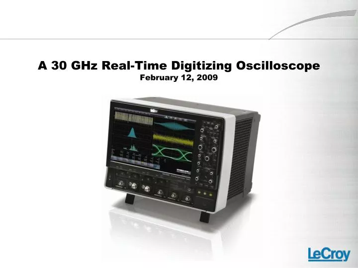
A 30 GHz Real-Time Digitizing Oscilloscope February 12, 2009. Why Would You Need 30 GHz? Bandwidth requirements related to signal speed. 5 th harmonic. Power spectral density (dB). This plot shows Power Spectral Density (PSD) as a function of bit rate.

E N D
Why Would You Need 30 GHz?Bandwidth requirements related to signal speed 5th harmonic Power spectral density (dB) • This plot shows Power Spectral Density (PSD) as a function of bit rate. • The plot is bounded by rise times that represent 0% (red line) or 100% (blue line) of a Unit Interval (UI) • Typically, serial data rise times are ~30% of a UI. There is significant PSD beyond the 5th harmonic frequency • Using an oscilloscope with bandwidth of 3x the bit rate or higher will show more frequency content Normalized frequency in units of bit rate
Bandwidth limiting of a 3 Gbps signal demonstrates need for more bandwidth 7.5 GHz bandwidth limited (2.5x bit rate) 9 GHz bandwidth limited (3x bit rate)
Serial data standards ≥2.5 Gb/s Minimum bandwidth requirements
Serial data transfer rate increases drive“Moore’s Law of Oscilloscope Bandwidth” Data transfer rate doubles every 3 years • As serial data transfer rates increase, the unit interval decreases and the rise time decreases, driving the need for more oscilloscope bandwidth
“Moore’s Law of Oscilloscope Bandwidth”Driven by Increasing data transfer rates and decreasing rise times “Moore’s law for bandwidth Oscilloscope bandwidth 1st generation (6-8 GHz) 2nd generation (13 - 16 GHz) • Problem – Serial data transfer rates and rise times of serial data signals require doubling of oscilloscope bandwidth every three years • Reality – Oscilloscopes must stay ahead of this curve while using the devices driving the curve
Methods for increasing oscilloscope bandwidth • DSP bandwidth boosting (stretching) • Apply a digital filter to the acquired waveform that has a response which peaks near the cutoff frequency of the input amplifier • Peak in the filter response pushes the 3dB point up in frequency • Can increase high frequency noise • Sampling rate must be > 2X the boosted frequency • Limited boost range based on the transition band of the input amplifier • Bandwidth interleaving • Utilize RF hardware to digitize the signal in different frequency bands • Use DSP filters to combine the separately digitized bands into one waveform sampled at 2x the rate • Front end amplifiers are always operating comfortably in rated frequency range • Reduces channel count but doubles the bandwidth • No additional increase in high frequency noise • Uses standard RF components (mixers, filters, amplifiers)
DSP bandwidth boostingNot the preferred method for increasing bandwidth DSP filter response Amplifier response 0 -10 -20 Boosted response -30 -40 f fboosted • Note: DSP “boost” or “stretch” should not be confused with other uses of DSP in oscilloscopes, such as to make minor response changes to match the response of channels and gain ranges or adjust phase delay. In the latter cases, DSP will provide signal fidelity improvements, not reductions.
DSP bandwidth boosting is not a viable solution for meeting market demands “Moore’s law for bandwidth Oscilloscope bandwidth 1st generation (6-8 GHz) 2nd generation (13 - 16 GHz) • Tektronix attempted to keep up with “Moore’s Law of Oscilloscope Bandwidth” using a DSP boost (see yellow dotted line) • Unfortunately, the impact was limited, and oscilloscope bandwidth was again insufficient to meet market demand
Digitizer InterleavingAn accepted method to increase SR and memory • Bandwidth set by front-end amplifier • Lower speed digitizers and memory interleaved • Improves sampling rate of A/D • Multiplies A/D converter sampling rate Front-end amplifier ADC’s memory
Bandwidth InterleavingAn innovative method to stay ahead of the BW curve • Separate signal into frequency bands • Down-convert high band to low frequency • Digitize down-converted and low-band simultaneously • Use DSP to compensate delay, phase and amplitude and combine bands 16 – 30 GHz 0 – 16 GHz 31.25 GHz LO 1 – 15 GHz 40 G sa/s ADC’s memory 30 GHz @ 80 G sa/s DSP channel combiner
DBI allows oscilloscopes to keep up with “Moore’s Law of Oscilloscope Bandwidth” DBI 1st generation (6-8 GHz) 2nd generation (15 - 16 GHz) • LeCroy’s DBI enables oscilloscopes to remain ahead of the bandwidth curve using current generation chip technology (solid yellow line)
LeCroy oscilloscope design allows for easy upgrade from 4 to 30 GHz bandwidth WaveMaster 20 to 30 GHz acquisition board hardware just adds DBI modules and 2.92mm front panel connectors WaveMaster 4 to 16 GHz acquisition board hardware
LeCroy WaveExpert sampling oscilloscope Measurement of “golden” step response Input Step measured with WaveExpert Sampling Scope with 70 GHz sampler Usually subtract the input risetime from the measured risetime to get the “scope only” risetime 15
Step response measured on 30 GHz WaveMaster 830 Zi (DBI) oscilloscope • Shape of step and rise time value closely correlate with sampling scope
Step response measured on 30 GHz WaveMaster 830 Zi (DBI) oscilloscope • Oscilloscope bandwidth (top plot) shows response out to 30 GHz.
Conclusion • Bandwidth requirements are being driven by increasing transfer rates (and decreasing rise times) • Oscilloscope hardware performance (amplifiers and A/D converters) is set by the current technology • Next generation hardware must be measured by current generation technology • Oscilloscope bandwidth is being driven by a “moore’s law” which requires a doubling every 3 years • Bandwidth stretching using DSP cannot keep up with the bandwidth need and has limited performance • LeCroy’s Digital Bandwidth Interleaving (DBI) enables the doubling of current technology enabling measurements on next generation hardware • LeCroy’s DBI is the best way to achieve high bandwidth with appropriate signal fidelity