Download
1 / 1
10 likes | 131 Vues
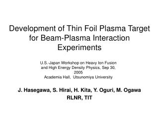
Interaction of T-10 Plasma with Impurity. V.Yu. Sergeev 1 , V.M. Timokhin 1 , V.G. Skokov 1 , B.V. Kuteev 2 , 1) State Polytechnical University, 2) Nuclear Fusion Institute, Russian Research. Abstract. Motivation. Experimental setup.

E N D
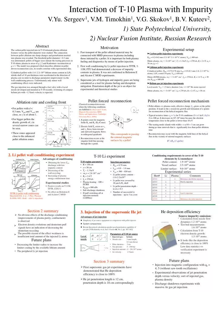
Interactionof T-10 Plasma withImpurity V.Yu. Sergeev1, V.M. Timokhin1, V.G. Skokov1, B.V. Kuteev2, 1) State Polytechnical University, 2) Nuclear Fusion Institute, Russian Research Abstract Motivation Experimental setup The carbon pellet injected into in T-10 tokamak plasma ablation features versus the pellet diameter were studied. The connection between pellet ablation rate sharp changes and perturbation inserted into plasma was revealed. The threshold pellet diameter ≈ 0.3 mm was determined: pellets of bigger sizes initiate the tearing processes in T-10 ohmic plasma in areas of q ≤ 2 and Kadomtsev reconnection at q = 1. The model was proposed which describes ablation in pellet driven reconnection case, its results correlate with experimental data. Cylindrical pellets with (1.6–2.2)·1019 lithium atoms content in LiN3 nitride shell of 10 μm thickness were accelerated in the direction of plasma core in order to discharge parameters improvement via the wall conditioning process. Unfortunately only minor wall conditioning effects were indicated. The gas injection was arranged through a fast valve with a Laval nozzle developed and mounted at T-10 recently. A forming of compact helium jets with ~1.5 km/s velocity is expected. • Fast transport of the pellet ablated material may be connected with MHD processes in plasma including those initiated by a pellet. It is important for both plasma fueling and diagnostics by means of pellet injection. • First wall conditioning by Li pellet injection in TFTR, T-11M, FTU had demonstrated a decrease of impurity contents in plasma. It was not confirmed in Heliotron E and Alcator C MOD experiments. • Supersonic jets of hydrogen and impurity gases are being considered as a tool for plasma fueling and disruption mitigation. Penetration depth of the jet is an object for experimental and theoretical studies ►Carbon pellet injection experiments Dpel = 0.2-0.62 mm (1.9·1017-5.1·1018 C atoms), Vpel ≤ 400 m/s Ohmic plasma, <ne> ≈ 21013 cm-3, Te = 1.2 keV, Ipl = 270 kA, Bt = 2.4 T, aL= 30 cm, qL = 3 ►Lithium pellet injection experiments Cylindrical pellets: Dpel = 0.75-0.78 mm, Lpel = 0.9±0.1 mm (1.6–2.2·1019 Li atoms), LiN3 coated (10 µm), Vpel ≤ 650 m/s Ohmic+ECRH plasma, <ne> ≈ 31013 cm-3, Ipl = 270 kA, Bt = 2.4 T, aL= 30 cm, PECRH = 800 kW ►Helium gas jet injection experiments Laval nozzle: Vjet≈ 1.5 km/s, duration 2 ms, 1-3·1019 He atoms injected Ohmic plasma, <ne> ≈ 31013 cm-3, Ipl = 270 kA, Bt = 2.4 T, aL= 30 cm Pellet forced reconnection mechanism Pellet forced reconnection Ablation rate and cooling front Classical reconnection occurs when the following conditions are fulfilled (E. Priest and T. Forbs, Magnetic Reconnection, MHD Theory and Applications, Cambridge, University Press, 2000): • Pellet ablates => plasma cools, effective charge Zeff grows at the pellet position. It leads to the η resistivity growth and formation of x-points for reconnection of the helical magnetic flux • Typical resistive times τR=r2/η for T-10 conditions (Te 1 keV, Zeff 2) is 100 μs. It decreases in 103-104 times because the electron temperature close to the pellet is lower than 10 eV • The tearing mode islands with width w a/10 = 3 cm can grow during µs time intervals that is significantly less than pellet ablation time • Reconnection may occur with the magnetic field lines of the helical flux in the vicinity of rational magnetic surfaces • B*=Bq (1-qn/m) • For pellets with d < 0.3 mm, Vpel and Vcool are close, so γ is of about 1. • For bigger pellets the drastic growth of γ in several narrow zones can be seen. • These zones appeared close to the enhanced pellet ablation zones. • X-points exist for magnetic fields Bx and By (Bz=Const) • Electric field Ez exists or vx and vy flows form inward and outward magnetic flows in orthogonal quadrants • Reconnection occurs at the singular field line passing through the x-point. This corresponds to passing the rational magnetic surfaces by a pellet! 2. Li pellet wall conditioning experiment T-10 Li experiment Conditioning requirements to cover of the T-10 elements by Li monolayer Advantages of conditioning T-10 regime parameters • R = 150 cm • a = 30 cm • Te ~ 1.3 keV • <ne> = 2.8·1013cm-3 • Bt = 2.4 T • Ip = 270 kA • Plasma heating – OH + ECRH • PECRH = 800 кВт • Soft discharge shutdown • D puff switching off at injection moment (t=600ms) Injection parameters • Dpel = 0.78 mm • Lpel = 0.8 – 1.0 mm • Vpel = 500 – 650 m/s • Lipellet atoms content – (1.6-2.2)x1019 • Li pellet was covered by10 mLiN3shell • Li pellet penetration depth – tor/a = 0.3 • Number of successful Li injections – up to 3 in a row 1.9·1019 atoms Pellet content: Obtaining the lower Zeffdischarge with low impurity content Vessel surface: 2.5·1020 atoms Limiter surface: 9.0·1017 atoms Decreasing of the wall recycling Experimental series Increasing of plasmaenergy confinement time Experimental studies Positive results on T-11M, TFTR, CDX-U time, s time, s No effect on Heliotron E and Aclator C MOD TFTR Li pellet wall conditioning Mansfield D.K. et al., J. Phys. Plasmas 3(1996) 1892 (bold – after Li injection) Section 2 summary He deposition efficiency 3. Injection of the supersonic He jet No obvious effects of the discharge conditioning (improvements of plasma purity, confinement) is observed Ш Source impurity emission: Advantages of jet injection • Calculation from nozzle flow Simplicity of jet source equipment in comparison with pellet injector dynamics: 1.2·1019 atoms System compactness Electron density evolutions and deuterium puff signals have an indication of decreasing the deuterium recycling • Test bed measurements: Ш 1.6·1019 atoms Recent theoretical calculations predict good penetration capability of gas jets [V.Rozhansky et al, Nucl. Fusion46, No 2, pp. 367-382] • Calculation from T-10 electron density growth: The possible reason of the effect weakness is insufficient total amount of the injected Li atoms Parameters of T-10 jet source Ш Injected gas - helium Laval 1.5·1019 atoms • Future plans nozzle • Nozzle size - 3 mm length, It looks like the deposition efficiency is close to 100% 0.3 mm throat • Decreasing the limiter radius to increase the limiter coating by the available lithium amount • Pulse duration - 2 ms Low data statistics => verification experiment is necessary • Gas pressure - 5 - 100 bar • Injection amount - (1 - 20)·1019 atoms • The peripheral Lijetinjection • Jet velocity - 1.5 km/s Future plans Section 3 summary Injection into magnetic configuration with qa = 4; 5 (without saw-tooth oscillations) • First supersonic gas jet experiments have demonstrated that He deposition efficiency is close to 100% Ш Experimental observations of jet penetration depth versus velocity, sort of injected gas, plasma density • He jet penetration length is 12 cm, penetration depth is 18 cm correspondingly Ш Discharge shutdown experiments with massive Ar gas jet injection •