Download
1 / 28
280 likes | 460 Vues
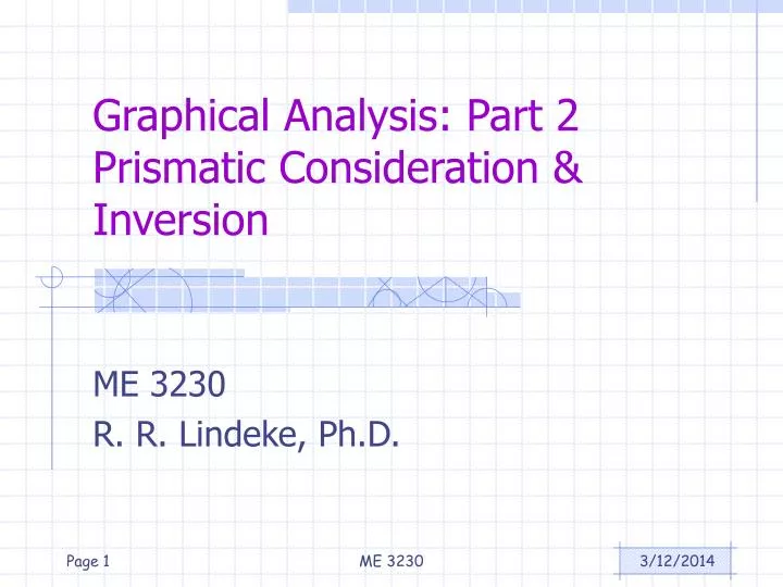
Graphical Analysis: Part 2 Prismatic Consideration & Inversion. ME 3230 R. R. Lindeke, Ph.D. Topics:. Dealing With Crank Sliders Position Velocity Acceleration Beyond the 4-Bar Linkage Drivers from outside the Primary Closures. Lets Look at Problem 2.6.

E N D
Graphical Analysis: Part 2Prismatic Consideration & Inversion ME 3230 R. R. Lindeke, Ph.D. ME 3230
Topics: • Dealing With Crank Sliders • Position • Velocity • Acceleration • Beyond the 4-Bar Linkage • Drivers from outside the Primary Closures ME 3230
Lets Look at Problem 2.6 • This is a Simple Crank Slider and lets add a point D4 (we will define vC4/D4 as the Slider Velocity) • Link AB = 60mm, Link BC = 200 mm • 2 = 100 rad/s (about 955 RPM) ME 3230
What we “Know” • Velocity Pole (o) includes points A2, A3, D3, D4 • vB2/A2 = 2 x rB2/A2 = 100 X 60 = 6000 mm/s (direction is normal to A2B2) = vB2 = vB3 • vC4/D4 is Horizontal • vC3 + vC3/B3 = vA2 + vB2/A2 • vC3/B3 = 3 x rC3/B3 (direction is normal to B3C3) ME 3230
Summarizing Velocity Analysis: • Vc/d = slider velocity = 45 * 100 = 4500 mm/s • Vc/b = 75*100 = 7500 mm/s = 3 * rc/b • Therefore, 3 = 7500/200 = 37.5 rad/s • Its direction is from rc/b to vc/b or CW ME 3230
Continuing: ME 3230
Graphically: • aC4/D4 – Slider Acceleration = 24.844*10000= 248440 mm/s2 • 3 = atC3/B3/rC/B= 210940/200 = 1054.8 rad/s2 ME 3230
One that Involved “Imaging” ME 3230
Drawn to scale: ME 3230
“Knowns”: • vB2 = vB2/A2 + vA2 = 2 x rB/A + 0= 20 rad/s * 0.5” = 10”/s (115-90)= 10 25”/s • vC3 = vB2 + vC3/B3 wherevC3/B3 = 3 x rC/B (direction normal to rC/B) • And vC4 = vD4 + vC4/D4 = 0 + 4 x rC/D where direction is normal to rC/D • vF5 = vE + vF5/E5 wherevE5/F5 = 5 x rF/E (Direction Normal to rF/E) • vF/’G’ = Slider Velocity is Horizontal ME 3230
We “Build” Velocity Image to get Pt E Used Similar Triangles rotated 90 CW and Scaling factor: 1.318/2 for each side (diameters of construction circles) vE/B = 1.186* 5 = 5.93”/s vE/C = 1.582 * 5 = 7.91”/s vC/B = 1.318 * 5 = 6.59”/s ME 3230
With Values: • vc = 1.639*5 = 8.195”/s344.03 • vE = 2.938*5 = 14.69”/s7.76 • 3 = vC3/B3/rC/B = 6.59/2 = 3.295 rad/s CCW • 4 = vC4/D4/rC/D = 8.915/.95 = 8.626 rad/s CW ME 3230
Finding the “F” Velocities: • vF5/E5 = .401*5 = 2.005”/s98.107 • 5 = vF5/E5/rF/E = 2.005/2.5 = 0.802 rad/s CCW • vF6/’G6’ = Slider velocity = 2.967*5 = 14.835”/s ME 3230
On to Acceleration (Knowns) ME 3230
Acceleration of Pt. B: • aB = 2.828*25 = 70.7”/s2340 ME 3230
Attacking Accel. Of Pt C: ME 3230
Leads to: • aC’ = 121.475308.45 in/s2 • atC4/D4 =3.952*25 = 98.8 in/s2 • 4 = 98.8/.95 = 104 rad/s2 • atC3/B3 = 2.726*25 = 68.15 in/s2 • 3 = 68.15/2 = 34.075 rad/s2 ME 3230
Next We will us an “Acceleration Image” approach for Pt. E • The Acceleration Image Triangle “side ratio” is aC/B/rC/B = 2.861/2 = 1.4305 • So: aE/B = 1.4305*1.8 =2.5749 • & aE/C = 1.4305 * 2.4 = 3.4332 • This lets us set Point e’ for E’s acceleration and branching to Pt. F’s acceleration ME 3230
Leads to: Thus aE = 5.354*25 = 133.85”/s2 @ 347.354 ME 3230
Graphically: aF = 5.122*25 = 128.05”/s2 5 = (1.175*25)/2.5 = 11.75 rad/s2 CW ME 3230
A Final Issue: • Driven Link Not in the Primary Linkage Closure (Primary 4-Bar Linkage) • Typically this means “solution by Inversion” is required • We will drive the mechanism from the primary linkage • We will use a Unit Rate for the inverted driver ME 3230
The Rest of the Technique • We Need to learn the position of a Point of Interest where the primary linkage meets the (real) Driver Linkage (since we will not necessarily have the actual geometry of interest in the inverted system) • This “Coupler Point” then must be traced • The Pose most closely approximating the desired “real driver” position when driven from the inversion is selected. • Using this geometry, we solve the Velocity/Acceleration problem working from the inverted driver link • We Find the “Proposed” Velocity of the Actual Driver Link • We generate an Inverted Velocity of the Driver Link to real Driver Velocity “Scaling Ratio” • All calculated Velocities and Acceleration found are multiplied by this scaling ratio to get actual values for the links and points ME 3230
Coupler Curve of Pt D generated using Catia’s DMU Kinematics Modeler ME 3230
Using this Modeler • We can get Coupler Curves of Points of Interest • We can get plots of actual Velocities, Accelerations, etc. From the Linkage in Motion (graphically) • We can generate Videos of the Linkage in Motion ME 3230
A Short Video: Click to Play Video: ME 3230