Download
1 / 57
620 likes | 1.15k Vues
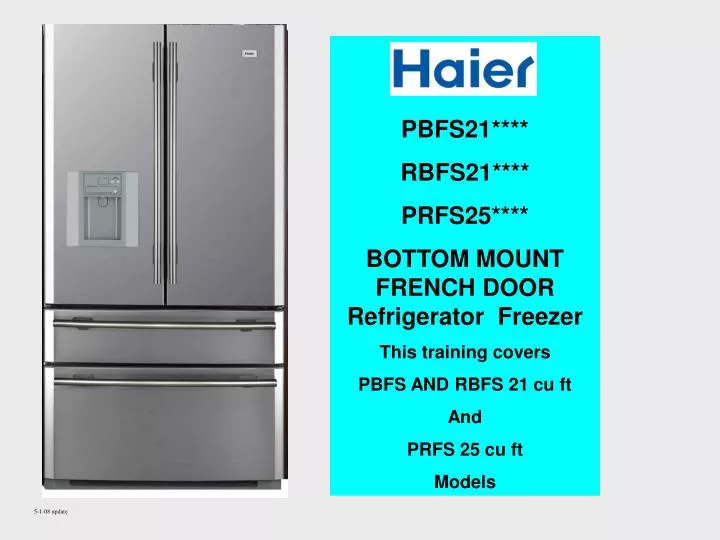
HAIER PBFS21**** RBFS21**** PRFS25**** BOTTOM MOUNT FRENCH DOOR Refrigerator Freezer This training covers PBFS AND RBFS 21 cu ft And PRFS 25 cu ft Models. 5-1-08 update. HAIER PBFS21**** RBFS21**** PRFS25****

E N D
HAIER PBFS21**** RBFS21**** PRFS25**** BOTTOM MOUNT FRENCH DOOR Refrigerator Freezer This training covers PBFS AND RBFS 21 cu ft And PRFS 25 cu ft Models 5-1-08 update
HAIER PBFS21**** RBFS21**** PRFS25**** BOTTOM MOUNT FRENCH DOOR Refrigerator Freezer Service Training Programs include: Operation Door Components Machine Compartment Fresh Food and Freezer Compartments Control Module Components Quick Check Reference
Model Designations Bottom Mount 21 cu ft Refrigerator / Freezer P B F S 21 E D A W W: White S: Stainless B: Black V: Virtual Stainless A: Production Series D: Dispenser I: Icemaker E: Elite S: Supreme T: Plus 21: Capacity S: Spill-proof shelving F: Four doors B: Bottom Mount Freezer P: Phoenix series R: Standard series
MODEL FEATURES PBFS21E*** - PRFS25E EXPRESS FREEZE EXPRESS CHILL WATER FILTER WATER DISPENSER ICE MAKER ENERGY STAR – VARIABLE SPEED COMPRESSOR
MODEL FEATURES PBFS21T*** WATER FILTER WATER DISPENSER ICE MAKER ENERGY STAR – VARIABLE SPEED COMPRESSOR
MODEL FEATURES RBFS21S*** BAR GRAPHICS FOR UPPER COMPARTMENTS NON-ENERGY STAR – SINGLE SPEED COMPRESSOR NO Dispenser or Water Filter
CONTROLS Freezer – Fresh Food Compartments FREEZER – 7 temperature settings. –6° ~+ 6° F More bars indicate colder temperatures. Press <-> to adjust. EXPRESS FREEZE* – Increases evaporator fan speed by approximately 10%. The function will reset to normal operation after 4 hours. Temperature setting cannot be changed when EXPRESS FREEZE is activated. Temperature will not drop below set temperature. *Not applicable to all models
CONTROLS Freezer – Fresh Food Compartments REFRIGERATOR – 7 Temperature settings. 34°~ 46° F More bars indicate colder temperatures. Press < - > to adjust. EXPRESS CHILL* - Increases evaporator fan speed by approximately 10%. The function reset to normal operation after 4 hours. Temperature setting cannot be changed when EXPRESS CHILL is activated. Temperature will not go below the set temperature. *Not applicable to all models
CONTROLS Freezer – Fresh Food Compartments N M K L E F G J FAHRENHEIT / CELSIUS - F° / C° * Press the F - G - J keys at the same time and hold for 3 seconds. Chime will sound indicating mode change. SABBATH MODE Press the E and L keys at the same time and hold for 3 seconds. Chime will sound indicating indicating the mode is activated. Press and hold the same keys to deactivate. DOOR OPEN ALARM – all models If the door or drawer remains open for 60 seconds, the door open alarm will sound and repeat on 30 second intervals. *Not applicable to all models
CONTROLS Freezer – Fresh Food Compartments N M K E F G J ICEMAKER ON - OFF Press the G - J keys at the same time and hold for 3 seconds. Chime will sound indicating mode change. Express Freeze indicator E will flash on and off when the icemaker is OFF FILTER RESET – FILTER CHANGE* The Change Filter indicator (N) will activate on 6 months intervals as a reminder to change filter. After changing filter, press and hold FILTER RESET (M) for 3 seconds to reset. The icemaker and water dispenser will not function if no filter is in place. POWER OFF MEMORY During a power outage, all functions are restored to the last set modes. *Not applicable to all models
CONTROLS Freezer – Fresh Food Compartments F G K DEMONSTRATION MODE* ! ! VERY IMPORTANT ! ! A “DEMO MODE” is programmed into the control panel. Pressing and holding the F, G, and K keys at the same time for 3 seconds will activate the DEMO MODE. The chime will sound and the compressor and evaporator fan will be inoperative. The lights will remain operative. By pressing the same keys again for 3 seconds will release the DEMO MODE. * Do not confuse with SABBATH MODE
CONTROLS Dispenser Control LOCK – Press and hold 3 seconds. When locked, the clock indicator is OFF, the water dispenser will not activate. Toggle function off / on by holding the LOCK button 3 seconds. TIME – Press and hold both buttons for 3 seconds to adjust time. After the chime, the left button changes hours. The right button changes minutes. Press and hold both buttons for 3 seconds to set time.
DOORS Freezer Door Removal 1 - Remove upper control panel 2 - Disconnect electrical connections 3 – Disconnect water line 4 – Remove hinge and lift door off of lower hinge ! ! ! NOTE ! ! ! A production change has moved the water line union to the backside of the cabinet. The union must still be disconnected in order to remove the door. 2 3 screws 1 4 3 Remove black retainer clip from one end of connector Push inward on white collar and tubing holding collar in Pull tubing out Replace by pushing tube fully in then replacing clip
DOORS Doors – Handle Removal Handles are held in place with an Allen head set screw on the side of the handle If handles are loose, tighten set screw Be Careful not to damage door panel or handle Door Panel Mounting Stud Remove the Allen head set screw at each end of the handle then pull handle outward
DOORS Door Alignment / Cabinet Leveling Leveling legs must be firmly against the floor in order to properly align the doors. Door hinges are not adjustable. Door height is adjusted by adding shims under each door. Raise the door and insert shims as needed Shims are supplied in the owners installation packet
DOORS Door Closer Apply a small amount of grease here The door closer holds the door in the closed position. Closers are mounted on the bottom of both doors Bottom door hinges have door closer cam Apply a small amount of grease here
CONTROL BOARDS Mother Board / Power Supply Mother Board with Central Processing Unit Low voltage circuits Fan motors, sensors, switches, controls Line Voltage Circuits Power Supply Board
CONTROL BOARDS Mother Board Line Voltage Connectors This information is provided in the service manual and diagrams on the Parts and Service web site
SENSORS Error Codes / Specifications 1 (3)
SENSORS Error Codes / Specifications Fresh Food / Drawer / Ambient Sensors Freezer / Icemaker / Defrost Sensors
THERMAL SENSORS remove / replace Sensor as mounted in Fresh Food, Freezer and Convertible Compartments DO NOT STRIP INSULATION Insert one end of replacement sensor wiring and one end of harness into connector Arrange connectors and sensor in cover and replace cover to cabinet wall Squeeze connector with pliers to complete connection Button should be fully depressed A small amount of sealant will leak out around wires making connection moisture resistant
THERMAL SENSORS Temperature Control / Damper Fresh Food Damper Test Damper is located in bottom of fresh food air tunnel
THERMAL SENSORS Temperature Control / Damper Door switch OUT set control for coldest setting The damper will be fully CLOSED Fresh Food Damper Test Damper is located in bottom of air tunnel
DISPENSER Dispenser Service WARNING Remove HIDDEN screw A mounting screw is hidden behind the control panel decal and must be removed before attempting to remove the control panel. The film can be removed by using a sharp knife to carefully lift a corner and then gently pulling the film up. After removing the HIDDEN SCREW, push in on sides of dispenser frame or use a putty knife to release clips under edge of frame to release clips then pull outward Dispenser lamp 15 watt miniature base Christmas tree type lamp Will turn off automatically after 4 hours
DISPENSER Dispenser Service PC Board Remove screws (4) to replace pc board Electrical connector is multi-pin push connector Red Arrows indicate locking tabs Dispenser Activator Switch is held in place with clips.
DISPENSER Dispenser Service Dispenser Activator Switch is held in place with clips. Be certain the bottom electrical connector is fully seated
DISPENSER Chilled Water Reservoir Water reservoir is located behind the lower drawer in Fresh Food compartment Water Filter Air return to evaporator
DISPENSER Water Filter Water is turned Off to the dispenser and icemaker when the filter is removed Automatic Filter Shut Off When the filter is inserted and rotated, an activator cam on the filter pushes the shut off inward to allow water to flow Filter Removal Activator Cam on Filter
WATER SOLINOID remove / replace All water flows through the water filter before being routed to the icemaker or dispenser. There are 3 solenoid valves which have color coded rings. The single primary valve supplies water to the filter (white ring). The water then returns to the secondary valves (black ring). The valve feeding the dispenser is designated with a green ring. The icemaker with an orange ring. All solenoids have a resistance of approximately 385Ω and are replaced as an assembly. To release the water line, push in on the tubing and colored fitting. Holding the fitting in, pull the line out. *Valve shown upside down From reservoir To Dispenser Anti-kink springs on all lines To Icemaker Primary Valve Secondary Valve Water Inlet
DISPENSER Water dripping from dispenser 1- Remove upper control panel 2- Disconnect water lines and clean and reinsert tubing into union 4 Remove black retainer clip from one end of connector Push inward on white collar and tubing holding collar in Pull tubing out Replace by pushing tube fully in then replacing clip
Fresh Food Doors 4 Left door flap swings inward when left door is opened Action is done with the door catch on the top of the fresh food compartment Door flap has a heater prevented to condensation
Fresh Food Doors Flap Heater Electrical Connection for door flap heater
Fresh Food Doors Flap Heater Door flap heater Mullion Heater RUN TIME is managed through the mother board and monitors humidity sensor readings, ambient temperature and door openings. Actual RUN TIME cycles off and on and varies in duration.
CENTER MULLION Remove / Replace / Heater A foil heater is located in the mullion to prevent sweating on the divider Remove screws to access heater or remove divider Icemaker
CENTER MULLION Remove / Replace / Heater Use caution when removing front cover of mullion not to break locking taps along each side Heater
CENTER MULLION Remove / Replace / Heater Remove this block to feed wires connectors through mullion
ICEMAKER Manual Test Press < Freezer and > Refrigerator buttons for 3 seconds. Icemaker will start a harvest and fill cycle
ICEMAKER Remove / Water Fill Tube Icemaker is held in place on 4 tabs Remove locking screw driven in front tab then pull icemaker forward The icemaker fill tube has a heater which is wired into the cabinet
ICEMAKER Water Fill Test / Adjust 65 Water Fill Test 6.5 Seconds 160ml -- 5 1/3 oz Water Fill Adjust Press and hold Freezer < > and Refrigerator < > buttons for 3 seconds. Time will be shown on the Freezer display in seconds. Adjust by ½ second intervals. 65 means the water fill time is 6.5 seconds. Press the Freezer < > buttons to increase or decrease the water fill time. The default setting is 6.5 seconds WARNING Always check the water fill level after replacing the icemaker or water fill valve 160ml
ICEMAKER Icemaker OFF / ON To turn icemaker OFF In unlock mode, press and hold FREEZER> and REFRIGERATOR < The EXPRESS FRZ indicator will flash off an on when the icemaker is off Repeat to restart
EVAPORATOR FAN MOTOR Remove / Replace Evaporator Air Tunnel Housing Remove 2 screws then lift out bottom first Air Tunnel Housing
EVAPORATOR FAN MOTOR Remove / Replace Evaporator cover must be pulled forward to access evaporator fan motor electrical connections Remove mullion for easier access Air Tunnel Housing
EVAPORATOR Evaporator Access After removing evaporator fan housing, pull lower cover out and upward to access evaporator components air duct to fresh food compartment defrost heater Freezer compartment temperature sensor
EVAPORATOR Evaporator Components DEFROST SENSOR F5 failure code is indication of failure of defrost sensor sensor may be open or shorted accumulator defrost high limit fuse mounted on evaporator
EVAPORATOR Evaporator Area Wiring Defrost Heater Evaporator Fan Motor Defrost Sensor and thermal fuse
EVAPORATOR Adaptive Defrost Cycle • This is an Adaptive Defrost Circuit which monitors ambient temperature, humidity, door openings, and temperature variances (load). The time between defrost cycles will vary depending on the above conditions. • The defrost process resets every time power is disconnected to the refrigerator. The cycle is controlled through the microprocessor on the motherboard. After the first 4 hours of compressor run time, the refrigerator will start a defrost cycle. • DEFROST CYCLE TIMELINE • At defrost cycle START, the heater will turn ON. When the temperature of defrost sensor reaches 7°C / 45°F, the heater will turn OFF. • For an additional 7 minutes, the compressor and evaporator fan will remain off and the fresh food damper stays closed. • After the 7 minute pause, the compressor starts and operates for 5 minutes. The evaporator fan will remain off and the fresh food damper stays closed. • After 5 minutes of compressor run time, the evaporator fan motor will start recirculating air within the freezer compartment. The damper will remain closed. • 3 minutes after the fan starts, the fresh food damper will open, completing the defrost cycle. • - - - - - - - - - - - • If there is a failure within the defrost circuit (heater, thermal fuse, sensor) or if the defrost sensor does not reach 7°C / 45°F within 120 minutes, ED will be displayed on the door display and the compressor will reenter the cooling mode. A problem at the motherboard could also affect the defrost cycle. ED
COMPRESSORS PBFS21****, PBFS21T*** and PRFS25*** Models are Energy Star models and use a 3 phase variable speed compressor controlled through the mother board and a compressor inverter control. The inverter control shown below is mounted on the compressor terminals. RBFS21S*** models use a conventional single speed compressor with PTC and overload mounted on the compressor terminals. Compressor operation is controlled through relays on the motherboard. Compressor Inverter / Control
COMPRESSOR COMPARTMENT components Control circuit input from mother board to inverter Condenser outlet to heater loops Joint for heater loops around freezer and drawer mullions 3 phase variable speed compressor Compressor Inverter / Control 115vac feed to compressor from motherboard
COMPRESSOR COMPARTMENT Inverter Removal – Energy Star Models Only To remove inverter remove 1 screw and pull inverter box upward and to the left Remove this screw to remove inverter from compressor DO NOT REMOVE THIS SCREW
COMPRESSOR Electrical Diagnostics – Energy Star Models Only The compressor is a variable-speed motor controlled through a low voltage signal to the inverter. There is no output test to the compressor. Compressor winding test – approx 6.7Ω between all windings DO NOT ATTEMPT TO START COMPRESSOR WITH DIRECT POWER CONNECTION COMPRESSER WILL BE DAMAGED 2.5 – 3.5 vdc red to black 115vac black to white NO TEST POINTS No power applied until compressor load is sensed