Download
1 / 20
200 likes | 353 Vues
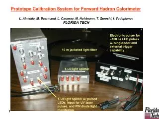
HCAL meeting DESY HH. A fast LED driver prototype for HCAL calibration. Proposal for calibration system. New LED driver with reduced crosstalk A tunable calibration light in the range 0 to 100MIP

E N D
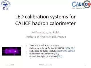
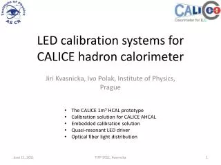
HCAL meeting DESY HH A fast LED driver prototype for HCAL calibration Ivo Polak, IoP Prague
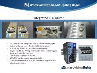
Ivo Polak, IoP Prague Proposal for calibration system • New LED driver with reduced crosstalk • A tunable calibration light in the range 0 to 100MIP • Simplification of the optical system: one LED -> one side emitting fibre, one row of scintillator tiles • PIN photo diode, do we need them?
Ivo Polak, IoP Prague LED driver strategy for SiPM calibration • At AHCAL prototype (uses SiPM), we used CMB, calibration system with UV-LED 400nm driven by very fast rectangular pulses (1ns rise/fall time). • Steep Rectangular waveform satisfied the needs to vary pulse-width, BUT creates lots of harmonics electromagnetic crosstalk! • We have found fixed pulse-width to about 6ns, we can go to use narrow band ->smooth waveform ≈ less RF interference = Quasi Resonant LED driver (single pulse)
Ivo Polak, IoP Prague Prototyping Used my lovely single side copper foil PCB We need more work on components optimization Quasi-Resonant LED driverLC circuit, heavily dumped • 2CH board • primary tested • With printed indictor 2ns pulse-width • Simulation pulse-width 5ns with 33nH inductance
Ivo Polak, IoP Prague QR LED driver Simulation oscilloscope oscilloscope
Ivo Polak, IoP Prague Simulation at 1.5V amplitude • XSC1: • Upper trace - sync pulse • Lower trace – voltage at LED hot end • XSC2: Lower trace LED current
Ivo Polak, IoP Prague Simulation at 3V • XSC1: • Upper trace - sync pulse • Lower trace – voltage at LED hot end • XSC2: Lower trace LED current
Ivo Polak, IoP Prague Prototype of QR LED driver
Ivo Polak, IoP Prague Tests shows more power on LED • We see response of PIN photodiode at oscilloscope • Amplitude up to 2mVpeak @ 50 Ω
Ivo Polak, IoP Prague Response to low amplitude • LED current (cyan) (voltage @ 10Ohm) • PIN response (yellow) • LED anode (violet)
Ivo Polak, IoP Prague Response to middle amplitude
Ivo Polak, IoP Prague Response to high amplitude • 200mA current at LED
Ivo Polak, IoP Prague Response to high amplitude • The Light from LED was optically blocked to PIN.
Ivo Polak, IoP Prague 2CH prototype Double sided PCB 2 QRLED driver 2PIN photodiode preamp Rate generator 1Hz to 10kHz Voltage regulators Amplitude control V-calib and T-calib interface
Ivo Polak, IoP Prague 2CH QRLED board There is a detail of two QRLED driver Printed inductors with taps, left is connected by tin joint Two trimmers equivalise delays between CH A and B
Ivo Polak, IoP Prague Principal schema of QRLed driver A A
Ivo Polak, IoP Prague LED Current View of the LED pulse for a small amplitude (0.6 A) Measured with 1GHz voltage differential probe and 1GHz scope TDS4104 at 1Ω smd resistor 4ns/div 0.5A/div
Ivo Polak, IoP Prague LED current • View of the LED pulse for a middle amplitude (1.0 A) • Measured with 1GHz voltage differential probe and 1GHz scope TDS4104 at 1Ω smd resistor • 4ns/div 0.5A/div
Ivo Polak, IoP Prague LED current • View of the LED current pulse for the highest amplitude (2.3 A) • Measured with 1GHz voltage differential probe and 1GHz scope TDS4104 at 1Ω smd resistor • 4ns/div 0.5A/div
Ivo Polak, IoP Prague Conclusion • QR LED driver is very promising technique to reduce Electro-Magnetic-Interferences • PCB of the two-channel QR LED driver is ready to further test • January - more test with Photodetectors • February – more assembled PCBs available • May – designing of multichannel system with light transfer in side-emitting fibres, mechanical integration to a new detector design