Download
1 / 23
240 likes | 476 Vues
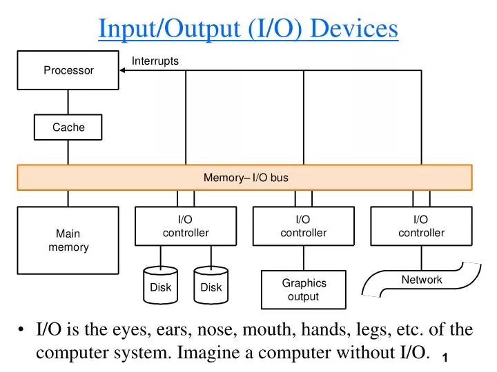
Input/Output (I/O) Devices. I/O is the eyes, ears, nose, mouth, hands, legs, etc. of the computer system. Imagine a computer without I/O. The Impact of I/O on Performance.

E N D
Input/Output (I/O) Devices • I/O is the eyes, ears, nose, mouth, hands, legs, etc. of the computer system. Imagine a computer without I/O.
The Impact of I/O on Performance • Elapsed time = CPU time = I/O time, suppose CPU time improves by 50% per year and I/O time doesn't improve.# of years CPU time I/O time Elapsed time % I/O time 0 90 10 100 10% 1 60 10 70 14% 2 40 10 50 20% 3 27 10 37 27% 4 18 10 28 36% 5 12 10 22 45% • The improvement in CPU performance over 5 years is 90/12=7.5, however the improvement in elapsed time is only 100/22=4.5, and I/O time has increased from 10% to 45% of the elapsed time. This clearly illustrates (מדגים את) Amdahl's Law. • If we care about system throughput (הספק) what interests us is I/O bandwidth (רוחב סרט), the amount of data transferred in a period of time. (A MB in I/O bandwidth is 1,000,000 bytes not 220 bytes)
Characteristics (מאפיינים) of I/O Devices Device Behavior Partner Data rate (KB/sec) Keyboard input human 0.01 Mouse input human 0.02 Voice input input human 0.02 Scanner input human 400.00 Voice output output human 0.60 Ink-Jet printer output human 50.00 Laser printer output human 200.00 Screen output human 60,000.00 Modem input/output machine 3.00-128.00 LAN input/output machine 500.00-6000.00 Floppy disk storage machine 100.00 Magnetic tape storage machine 2000.00 Magnetic disk storage machine 2000.00-10,000.00
The Mouse • The interface between a trackball mouse and the system is by counters that are incrementedor decremented, depending on the mouse's movement. The system must also detect when one of the mouse buttons isclicked, double clicked, held down,or released. Software reads thesignals generated by the mouse anddetermines how much to move, how fast, and what each mouse button action means. • The system monitors the status of the mouse by polling the signals it generates. Polling is constantly reading signals every n cycles. This is the simplest form of interface between processor and I/O.
Magnetic Disks • The magnetic disk or hard disk is a nonvolatile (לא מחיק) storagedevice. The disk is composed of rotating platters coated (מצופים)with a magnetic surface. Moveableread/write heads access the data on theplatters. • A magnetic disk is made out of a several (1-15)platters which are rotated (מסובבים) at 3600-7200 RPM (Revolutions Per Minute). The diameter of each platter is between 2 to 20 centimeters. Both sides of each platter is used.Each platter is divided into circles (1000-5000)called tracks, each track is divided into sectors (64-200). A sector is the minimum unit of data read or written. It is usually 512 bytes. • A floppy disk is a magnetic disk with 1 platter only.
Accessing Data on the Disk • To access data the read/write heads must be moved to the right location. All heads move together so every head is over the same track on every surface. All the tracks under the heads at a given time are called a cylinder. Thus the number of cylinders is the number of tracks on 1 platter. • To access data is a three stage process(תהליך תלת שלבי). The first step is to move the head over the right track. This is called a seek (חיפוש) and the time do do this is called the seek time. Average seek times are between 5-15 ms. Due to locality the real average time can be 25% of the advertised time. • Once the head is over the correct track we must wait for the right sector to rotate (להסתובב) under the head. This is called the rotational latency or rotational delay. The average latency is half way around the disk. Because the disk rotates at 3600 to 7200 RPM the average rotational latency is: 0.5/3600 = 0.000139 minutes = 0.0083 seconds = 8.3 ms (4.2ms for 7200RPM disks).
Disk Read Time • Smaller diameter (קוטר) disks are better because they can spin faster with less power, they are of course, more expensive. • The last stage of a disk access is the transfer time. The time to transfer a block of bits typically a sector. Transfer rates are between 3 to 20 MB/sec. Most disks today have built-in caches that store sectors as they are passed over. Transfer rates from the cache are up to 50MB/sec. • The control of the disk and the transfer between the disk and memory is handled by a disk controller, The overhead ofusing the controller is called controller time. • What is the average time to read or write a 512-bye sector, for a disk rotating at 7200RPM. The average seek time is 10ms, the transfer rate is 15MB/s, and the controller time is 1ms:10ms + 4.2ms + (0.5KB/15MB)sec + 1ms = 10 + 4.2 + 0.03 +1 = 15.23ms. If the seek time is only 2.5ms we have 7.73ms.
Buses: Connecting I/O to Processor and Memory • I n a computer system the memory and processor have to communicate, as do I/O devices. This is done with a bus. A bus is a shared link which uses one set of wires to connect multiple devices. • The 2 major advantages of the bus are flexibility (גמישות) and low cost. New devices can be added easily and only one set of wires is need to connect multiple devices. • The major disadvantage of the bus is that it is a bottleneck (צוואר בקבוק), all devices compete (מתחרים) for the bus and the bandwidth is relatively limited. • A bus transaction includes 2 parts: sending the address and receiving or sending data. A bus transaction is defined by what it does to memory. A read transaction transfers data from memory (to CPU or I/O device). A write transaction writes data to memory.
Input/Output Operations • The previous terms (הגדרות) can be confusing. To avoid this we will use the terms input and output, an input operation in inputting data from an I/O device to memory where the CPU can see it. An output operation is outputting data to a device from memory where the CPU wrote it. • The shaded part shows what partof the device is used (right for read, left for write). • An output operation involves3 steps: • Signal memory and I/O thata read transaction is to take placeand send the memory address andI/O location. • Read the data from memory. • Write it to disk.
Types of Buses • An input operation involves 2 steps: • Signal memory an I/O that a write transaction is to takes placeand send the memory address andI/O location. • Write from I/O into memory. • Buses are classified into 3 types: processor-memory busses, I/O busses, or backplane busses. • Processor-memory buses are short, high-speed to maximize memory-processor bandwidth. • I/O busses are long and can have many types of devices connect to them.They don't interface directly with memory but use a bus-adapter to interface the processor-memory bus. • Backplane buses are designed to allow processor,memory, and I/O to use the same bus.
Standard Buses • Processor-memory buses are proprietary (מיוחדים למחשב מסוים) while I/O and backplane buses are standard buses that are used by many computer makers. • In many PCs the backplane bus is the PCI bus and the I/O bus is a SCSI bus. Both are standard buses.
Synchronous and Asynchronous Buses • A bus is synchronous(סנכרני) if it includes a clock in the control lines and has a fixed protocol for communication that is relative to the clock. For example, a processor-memory bus performing a read from memory transmits (משדר) the address on the bus and after 5 clock cycles expects to have the data on the bus. • In synchronous buses the protocol is predefined so the bus can be very fast. There are 2 major disadvantages: Every device on the bus must run at the same clock rate and the bus must be short in order to have the clock run through it. • An asynchronous bus isn't clocked so it can connect many devices of varying clock speeds. To coordinate transactions on the bus a handshake protocol is used. Lets assume a device is requesting a word of data from memory. There are 3 control lines: • ReadReq: indicates a read request from memory. • DataRdy: indicates that the data word is now on the bus. • Ack: Used to acknowledge (לאשר) the ReadReq or DataRdy signals.
The Handshake Protocol • The steps in the protocol begin after the I/O device has asserted the ReadReq signal and sends the address over the bus: 1. Mem sees the Readreq, reads the address and sets Ack. 2. I/O sees the Ack line is set and releases the ReadReq and data lines. 3. Mem sees that ReadReq is low and drops Ack to acknowledge that. 4. Mem places the data on the data lines and raises DataRdy. 5. I/O sees DataRdy, reads the data from the bus and raises Ack. 6. Mem sees the Ack signal, drops DataRdy and releases the data lines. 7. I/O sees DataRdy go low, drops Ack which indicates that transmission is over.
Bus Performance • We want to compare the maximum bandwidth for a sync and async bus. The sync bus has a clock cycle time of 50ns and each bus transmission takes 1 cycle. The async bus requires 40ns per handshake. Each bus has 32 data lines. What is the bandwidth when performing one word reads from a 200ns memory. • Synchronous bus:1. Send the address to memory: 50ns2. Read the memory: 200ns.3. Send the data to the device: 50nsThus to read a 4 byte word takes 300ns, 4 bytes/300ns = 4MB/0.3sec = 13.3MB/sec. • Asynchronous bus: we can overlap several steps with the mem access:Step 1: 40nsSteps 2,3,4: max(3x40,200) = 200nsSteps 5,6,7: 3x40ns = 120 ns.Thus the transfer time is 360ns and the bandwidth is 11.MS/sec
Increasing the Bus Bandwidth • Data bus Width:Transfers of multiple words require less cycles. • Separate vs. Multiplexed address and data lines: Previous examples used the same wires for address and data. Using separate wires will make writes faster as the address and data are sent in 1 cycle. • Block Transfers: Allowing the bus to transfer multiple words without sending an address or releasing the bus reduce the time needed to transfer large blocks. • Suppose we have a synchronous bus that has a data width of 64-bits and clock cycle of 50ns and memory with an access time for the first word of 200ns and 20ns for additional words, what is the read bandwidth:1. Send address: 1 clock cycle2. Read memory: 220ns/50ns = 5 clock cycles3. Send data from memory: 1 clock cycleThus to read 8 bytes takes 350ns. 8bytes/350ns = 8MB/0.35secs = 22.85MB/sec
Obtaining Access to the Bus • How does a device gain access to the bus it wants to use? Without any control all devices will access the bus lines causing chaos (בלגאן). The solution is to have one or more bus masters. The master initiates transactions and controls who can access the bus. • The memory is usually a slave, as it just responds to read/write requests. • The simplest scheme is to have only one master, the processor. A device generates a bus request which is sentto the processor. The processor then decides if to grant access or not and controls the bus. The problemis that this ties up the CPU.
Bus Arbitration (בוררות) • A better scheme is to have multiple masters. Which master gets control of the bus is called bus arbitration. A device that wants to use the bus signals a bus request and waits until it is granted the bus. • Arbitration schemes have to balance two factors: bus priority, the highest-priority device gets the bus, and fairness all devices that want the bus will eventually get it. • There are several schemes but the simplest one is called daisy chainarbitration. If a higher-priority device sees that a lower-priority device has been granted the bus, it intercepts the signal and doesn't pass it on. There are several variants to the scheme that ensure some kind of fairness.
I/O Bus Characteristics Option High performance Low cost________ Bus width separate address and multiplex address and data lines data lines Data width wider is faster (32-bits) narrower is cheaper (8-bits) Transfer size multiple words require single-word transfer less bus overhead is simpler Bus masters multiple master (requires single master arbitration) (no arbitration) Clocking synchronous asynchronous
Interfacing I/O to Memory and Processor • In order for the processor to give commands to I/O devices it must be able to address the device and supply commands. Two methods are used to address I/O devices: • Memory-mapped I/O:parts of the address space are assigned to I/O devices. When the processor writes to these addresses the memory ignores them as they are mapped to I/O. The device controller that is mapped to the address reads the data and issues a command to the I/O device. The device writes to memory-mapped I/O to respond to the processor. • Special I/O instructions:Special instructions not available to users but only to the OS enable giving commands to I/O devices. • The simplest way for the processor to know if there is an I/O event is by checking in a loop. This is called polling. The device puts information in a status register or in memory-mapped I/O and the processor reads it.
Overhead of Polling • The disadvantage of polling is that it can waste the processors time. Lets see the overhead of polling in 3 devices, the overhead of a polling operation is 400 cycles and the processor has a 500MHz clock (500,000,000 cycles per second) • A mouse must be polled 30 times a second: So we need 30*400 = 12,000 cycles per second for polling. The overhead of mouse polling is 12,000/500,000,000 = 0.002% • A floppy disk transfers data to the processor in 16-bit units and has a data rate of 50KB/sec: (50KB/sec)/(2Bytes/polling) = 25K pollings/sec. Thus we need 25K*400 cycles per second for polling. (250,000*400)/500,000,000 = 2%. This is already significant. • A hard disk transfers data in 4-word units and can transfer 4MB/sec. (4MB/sec)/(16Bytes/polling) = 250K pollings/sec. Thus we need 100,000,000 cycles per second to poll the disk which is a 20% overhead. This is much to high.
Interrupt-Driven I/O • The overhead in a polling interface lead to the invention of interrupts to notify the processor when an I/O device needs attention from the processor. The interrupt is handled the same way as the exceptions we have seen before. When the interrupt is detected, control is transferred to the OS who only then polls the device. The CauseRegister is used to tell the processor which device sent the interrupt. • Interrupts relieve the processor of having to wait for the devices, but the processor still has to transfer the data from memory to the device. • If a disk transfer of 4-words takes 500 cycles what's the processor overhead?Cycle per second for disk = 250K (same as polling) x 500 = 125,000,000 cycles thus the overhead is 25%. But if the disk is in use only 5% of the time the overhead is 1.25%.
Direct Memory Access • But what if the disk is being used all the time? A device call the DMA (Direct Memory Access) is used. The DMA transfers data directly from memory to I/O without involving the processor. • There are 3 stages in a DMA transfer:1. The processor sets up the DMA by supplying it with the memory address and I/O device involved in the transfer.2. The DMA performs the transfer.3. The DMA notifies the processor (with an interrupt) that the transfer has completed. • What's the overhead of using DMA if the setup time is 1000 cycles and the completion interrupt takes 500 cycles? The average transfer from disk is 8KB, the disk is utilized 100% of the time. • Each DMA transfer takes 8KB/4MB/sec = 0.002 secs.So if the disk is constantly transferring there are 500 transfers per second which means there are 1500*500 processor cycles per second . The overhead is 750,000/500,000,000 = 0.2%
A Typical Desktop I/O System • Organization of the I/O on the Apple Macintosh 7200 series: