Download
1 / 32
320 likes | 420 Vues
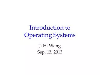
CMPT 300 Introduction to Operating Systems. Operating Systems Overview: Using Hardware. Memory. Modern computers use several kinds of storage. 1 nsec. registers. < 1KB. 8 MByte. 1.5 nsec. Cache. 6 nsec. Main Memory ( RAM volatile. ROM non volatile). 10 GByte.

E N D
CMPT 300Introduction to Operating Systems Operating Systems Overview: Using Hardware
Memory • Modern computers use several kinds of storage 1 nsec registers < 1KB 8 MByte 1.5 nsec Cache 6 nsec Main Memory ( RAM volatile. ROM non volatile) 10 GByte Flash Memory (non volatile, rewritable) 5 msec DISK 3000 GByte CD, DVD, USB memory stick
Memory Hierarchy • As you go down the pyramid • Decreasing cost per bit, Increasing capacity • Increasing access time, Decreasing frequency of access • Note that the fastest memory, sometimes referred to as primary memory, is usually volatile (register, cache, most or all of main memory) • Non volatile (continues to store information when the power is off) memory is usually slower. Usually not part of the CPU. Referred to as secondary or auxiliary memory. Examples flash memory (flash that holds the BIOS, or removable flash), internal and external hard drives, CD, tape, …
Registers and cache • Parts of the CPU • Register access speed comparable to CPU clock speed • In the most recent generations of CPUs cache memory may be as fast or as much as several times slower • Registers • (64x64 for 64 bit, 32x32 for 32 bit usual maximum) • Usually < 1 Kbyte • Cache • As much as 8Mbytes as little as none
Concept of Cache • Provide memory on the CPU that is slower that the registers, cheaper and larger than registers, but can be accessed must faster than main memory • The next few instructions, and data that will be needed will be loaded into cache in anticipation of faster access by the processor.
Cache and main memory CPU Registers Main memory Cache
Using Cache • Instructions (and data) are generally moved from main memory to cache in blocks, In main memory one of these blocks (N bytes of memory) is called a cache line • Cache has a series of slots, (N byes long, often 64 bytes) Each slot can hold a copy of one cache line in main memory. • There are many more cache lines of memory in main memory than there are slots in the cache memory. • Each time a copy of a new cache line is loaded into a cache slot, the contents of that slot is overwritten
Cache design • Cache size and Cache line size • Determined to optimize access time • Mapping function • Which cache lines may be loaded into which cache slots (can any line go in any slot or is there a mapping function to define rules governing which line can be place in which slot) • Replacement algorithm • When is a cache line in a cache slot replaced by another cache line
Hit ratio • A CPU access that finds its information in the faster cache memory is called a hit. • If it is necessary to also access the slower main memory (or lower level cache) to find the information then the access is not a hit it is a miss. • The proportion of accesses that are hits is called the hit ratio • Consider an example, • Assume that any access to the cache takes .01μs, any access to main memory takes 0.1μs (100 nsec) • Any instruction or piece of data not in cache will have to be accessed in main memory and moved to cache before being accessed (0.1+0.01)μs • For a hit ratio of x% what is the average memory access time
Cache Line size • As block size (cache line size) increases from a single byte the hit rate will, at first increase. • It is very likely that bytes near a needed byte will be accessed at about the same time • But as cache line size increases the number of lines decrease • As cache line size increases past it’s optimal value then the hit rate will begin to decrease • This happens when it becomes more probable that the next access will involve the cache line that was removed from the cache slot used for a recent addition • This also depends on the mapping function and replacement algorithm which determine which slot will be used for the next cache line moving into cache
Effect of Line size (example) NOTE: MB/s = 1/nsec * 1000
Cache specifications on common systems • Most modern systems have an onboard cache (like we have been discussing) called an L1 cache • Many modern systems also have a 2nd and / or 3rd level of cache between the L1 cache and the main memory called the L2 (L3) cache. • L2 cache was external to the CPU, on a separate chip on the motherboard, in systems as recent as pentiumII • In more recent systems L2 cache is in the CPU package (onboard) or part of the CPU itself (on die)
Multiple levels of cache: L2 CPU Main memory registers L1 cache (instructions) L1 cache (data) L2 Cache
Multiple levels of cache: L3 L L3 cache registers registers L1 cache (instructions) L1 cache (instructions) Main memory core1 L1 cache (data) L1 cache (data) L2 Cache L2 Cache core2
Modern Cache Architectures Shared cache requires more complicated cache controller Individual caches are more difficult to keep synchronized Core 2 Duo Core2 Quad Nehalem (i5, i7) AMD K10 (Phenom 9)
Main memory • RAM (random access memory) • Mostly volatile: contents lost when power cycles • May include a small amount of non volatile RAM (or ROM) that is often used to hold basic information • Bootstrap loader • BIOS (Basic input output system)
Disk • Hard disk • CD DVD Blu-Ray Disk storage is much cheaper that memory • (3GB memory or 2000GB disk about the same cost) • Access time for disk is at least one order of magnitude slower than for memory
Input / Output • Reading or writing data from a storage device is not simple • Each device has its own controller (hardware) • Each device is managed by a device driver (software to use the controller) • Device drivers are specific to hardware and to the operating system using the device • Input and output is SLOW in comparison to CPU operations.
Busy Waiting • Reading or writing data to a storage device is SLOW in comparison to the time it takes to complete one CPU operation • The CPU must send one or more instructions to the controller (device driver) to make the I/O device begin to read or write. These instructions tell the controller where to find the data and/or where to store the data • The CPU can then wait until the I/O operation is finishes. • While it waits the CPU will be in a loop • Each time through the loop the CPU will check a register in the controller to see if the I/O operation is complete • This is called busy waiting.
Alternatives to Busy waiting • CPU is a valuable resource, busy waiting does not efficiently use CPU resources • Want to use the CPU to execute other instructions while the I/O operation is completed by the I/O device (instead of executing the busy waiting loop) • To use the CPU for other calculations while to I/O device controller completes the I/0 operation we need to use interrupts (a mechanism to tell the CPU when the controller completes the I/O)
Interrupts • Interrupts are a mechanism by which other modules (memory, I/0, timers …) may interrupt the normal sequence of instructions being executed by the processor • Interrupts are a critical component of the operation of spooling and multiprogramming (more later). • Interrupts allow the transfer of control between different programs (remember the OS is also a program) • Interrupts can be generated by hardware (asynchronous) or by particular instructions in software (synchronous)
Some types of interrupts • I/0 • Signaling normal completion of an operation (read or write) • Signaling error during operation • Timer expiry • Begin regularly scheduled task • End task that has exceeded allocated time • Program generated • Instruction causes hardware error condition (divide by 0, overflow, illegal instruction or address, interrupt instruction …) • Hardware failure • Parity error …
Increase in efficiency With interrupts Time No interrupts B1 B1 Write Instruction Write Instruction CPU (processor) wait B2 ISR execution Complete Write B2 B3 B3
Interrupt example: Output (1) • Program executes until it reaches a write instruction • The write instruction sets up the hardware output device operation then leaves the output device controller (not the CPU) processing the output • The program continues execution of additional instructions (N+3 to N+7 next slide) • When the output hardware device completes the output operation it generates and sends an interrupt signal to the CPU signaling normal completion of output
Interrupt example Output (2) • When the presently executing instruction completes the program is interrupted • The registers and state are saved • An interrupt service routine completes the output operation • The registers and state are restored • The original program continues executing
Interrupt operation program ISR (interrupt service routine) Instruction N B1 Instruction N+1 Initialize hardware, Begin print Write instruction Instruction N+3 Save registers and state B2 Instruction N+5 Print complete Send interrupt Instruction N+7 Instruction N+8 Instruction N+9 Restore registers and state . : B3 Print hardware
Instruction cycle with interrupts START Interrupts disabled execute Fetch Interrupts enabled Decode Check for interrupt
Interrupt processing (1) • A device issues an interrupt request • The CPU (processor) finishes execution of the present instruction • The CPU tests to see if there is a pending interrupt, determines there is, and sends a acknowledgement to the device requesting the interrupt • The CPU saves registers and state to the stack (including the program counter register value) • The CPU loads the address of the appropriate ISR (interrupt service routine) into the address register
Interrupt processing (2) • The CPU executes the ISR • When the ISR is complete the saved register and state information is restored to the CPU registers • The program counter is reset to point to the next instruction • The original program continues execution REMEMBER: the time when an interrupt occurs is not known in advance!! Interrupts are asynchronous
How to find the ISR? • Each device, and each possible reason for an interrupt will have a different ISR, because different things need to be done • Each interrupt will send a particular signal (and/or use a particular hardware line). • The signal (and / or origin of the signal) will indicate which ISR should be chosen from the ISR vector • There may be a limited number of available lines / signals that must sometimes be shared between hardware devices (e. g. IRQ’s)
Interrupt Service Vector ISR (interrupt service routine) ISR vector To ISR A Interpret signal or line to choose interrupt To ISR B To ISR C To ISR D Save registers and state Restore registers and state