Download
1 / 8
90 likes | 636 Vues
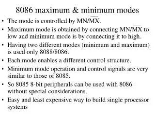
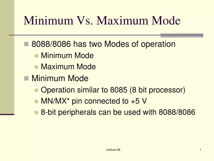
Minimum Vs. Maximum Mode. 8088/8086 has two Modes of operation Minimum Mode Maximum Mode Minimum Mode Operation similar to 8085 (8 bit processor) MN/MX* pin connected to +5 V 8-bit peripherals can be used with 8088/8086. Minimum Vs. Maximum Mode. Maximum Mode

E N D
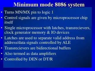
Minimum Vs. Maximum Mode • 8088/8086 has two Modes of operation • Minimum Mode • Maximum Mode • Minimum Mode • Operation similar to 8085 (8 bit processor) • MN/MX* pin connected to +5 V • 8-bit peripherals can be used with 8088/8086 Lecture 06
Minimum Vs. Maximum Mode • Maximum Mode • Enhanced Operation used whenever a coprocessor is used with 8088/8086 • MN/MX* pin connected to GND • 8288 Bus Controller required to generate extra signals Lecture 06
Summary Lecture 06
Memory Interface • Memory Pin Connections • Address Pins • Data Pins • Control Pins • Selection Pins Lecture 06
Memory Interface • Address Pins • Number of locations in memory determine the number of Address Pins • 4 K = 12 lines • 1 M = 20 lines Lecture 06
Memory Interface • Data Pins • Width of memory determines the number of Data Pins • 8 bit width = 8 lines • 1 bit width = 1 line Lecture 06
Memory Interface • ROM Control Pins • OE* or G* allows data to flow out • RAM Control Pins • WE* allows data to be written • OE*allows data to be read • Can have a single R/W* pin Lecture 06
Memory Interface • Selection Pins • CE* or CS* allows the RAM/ROM chip to be selected • Sometimes there are more than one CS* signal Lecture 06