Download
1 / 24
240 likes | 245 Vues
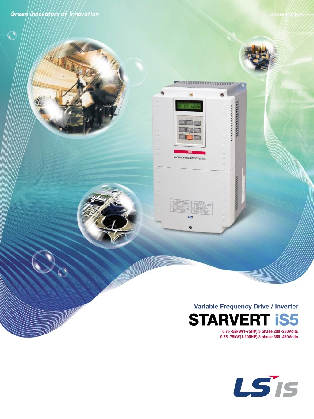
Precise vector control standard VFD Sensorless & sensored vector controller iS5 (0.75~75kW) keeps your application in more stable, durable and precise condition. And iS5 maximizes user-convenience with Auto Tuning, PID control, etc.<br>For More Information visit on:- www.seeautomation.com<br>Our Mail I.D:- sales@seeautomation.com<br>Contact Us:- 91-11-22012324 , 8144883403

E N D
Variable Frequency Drive / Inverter STARVERT iS5 0.75 -55kW(1-75HP) 3 phase 200 -230Volts 0.75 -75kW(1-100HP) 3 phase 380 -460Volts
Starvert iS5 Contents 02 Overview 04 Features & Selection Guide 06 Specifications & Wiring 08 Terminal Configuration, Keypad & Parameter Navigation 10 Program Parameter Descriptions 18 Dimension 20 Options, DB Resistor & Peripheral Devices 22 RFI Filters
Overview Standard features ■ kW / Voltage Ratings: •0.75~55kW, 200-230VAC, 3 phase •0.75~75kW, 380-480VAC, 3 phase ■ Enclosure: IP00 ~ IP20 ■ Inverter Type: PWM with IGBT ■ Control Method: Sensorless/Sensored Vector ■ 1~15kHz Carrier Frequency (1~8kHz. over 30kW) ■ 0~400Hz Output Frequency ■ Removable Keypad (Able to read & write parameters) ■ Intelligent Accel/Decel for Trip-Free Operation ■ Auto Tuning ■ 8 Multi-Function Inputs ■ 1 Multi-Function Outputs ■ Failure Relay ■ Built-in PID Control ■ Pre-Set Speeds ■ Wire Operation ■ Multi-step Programmable Run Patterns ■ Auto Torque Boost ■ DC Injection Braking ■ Stall Prevention ■ Built-In Braking Circuit for 0.75 ~ 7.5kW units Sensorless, sensored vector controlled iS5, keeps your application in more stable, durable and precise condition. Options ■ Communications Board: •RS-485 •DeviceNet •F-Net •ModBus-RTU •ProfiBus DP •Extended I/O Module -Sub-A Board: 3 Multi-Function Input 3 Multi-Function Output -Sub-B Board : Encoder Plus Input Encoder Plus Output -Sub-C Board : 3 Multi-Function Input 3 Multi-Function Output Aux. Analog Reference Frequency (Isolated) ■ Cable for Remote Keypad Operations ■ Dynamic Braking Units for 11~75kW Inverters ■ Dynamic Braking Resistors Application ■ Traverse ■ Draw ■ MMC (Mult Motor Control) ■ Converting ■ Material Handling ■ Web Processing ■ Fan/Pump Controls ■ Conveyors ■ Industrial Washing machine, etc. Conformity to global standards ■ UL and cUL listed for North America ■ CE marked for Europe ■ Quality process controlled by ISO9001, ISO14000 02
Starvert iS5 Extended I/O boards The iS5 has several additional I/O boards that can be easily mounted into the connection terminal on control board. Each I/O board is standardized for a specific I/O requirement. The three main I/O boards are "Sub-board A", "Sub-board B" and "Sub-board C". This helps system engineer to design most adequate and cost effective system using the exactly necessary number of I/Os and functions. It is extendable and changeable in case of system upgrade or change. The control parameters and detailed functions for these boards are not shown until any of them is inserted. Diversity of communication interfaces The iS5 provides most popular communication interfaces such as Device Net, Profibus DP, Modbus-RTU, RS485 and F-Net (LS proprietary protocol for LS PLC communication). The "DriveviewTM" software offers Window®based computer monitoring tool through RS-485 interface with graphic capture, keypad emulator, parameter edit, and text monitor. It is applicable for all LS inverters. Built-in PID control It is valuable in process control. The built-in PID algorithm controls flow, temperature, pressure, etc. through the proportional, integral and differential calculus between the feedback value and reference value in closed loop. The high speed CPU makes the calculation easy and fast. Sensorless vector control The iS5 adopts sensorless vector control algorithm, and it improves not only the torque control characteristics, but the speed controlability in an uncertain condition caused by the load variation as well. The iS5 especially generates strong torque at a low speed range as shown below. 03
Features & Selection Guide Auto tuning The auto tuning algorithm in iS5 sets the motor factors automatically. It brings the traditional commissioning difficulties mainly in low speed by the load variation and the low torque generation to a settlement. Optimum acceleration and deceleration To make a maximum torque during the acceleration and deceleration, so called "trip free" function is acting during acceleration and deceleration. Both of Acceleration and deceleration may cause a trip in case that it is manually programmed. The 32-bit DSP CPU monitors the current transition during the acceleration and deceleration to program an optimum curve that is under the triptrigering level automatically. Stopped CH1=2V DC 10:1 Stopped CH1=2V DC 10:1 CH3=5V DC 10:1 CH4=2V DC 10:1 CH3=5V DC 10:1 CH4=2V DC 10:1 1s/div [1s/div] NORM:1kS/s 1s/div [1s/div] NORM:1kS/s 3 3 Trip =Filter= =Offset= Ch1 : 0.00V Ch2 : 0.00V CH3 : 0.00V CH4 : 0.00V =Record Length= Main : 10k Zoom : 500 =Trigger= =Filter= =Offset= Ch1 : 0.00V Ch2 : 0.00V CH3 : 0.00V CH4 : 0.00V =Record Length= Main : 10k Zoom : 500 =Trigger= Smoothing : OFF BW : FULL Mode : AUTO Type : EDGE CH1 Delay : 0.0ns Hold Off : MINIMUM Smoothing : OFF BW : FULL Mode : AUTO Type : EDGE CH1 Delay : 0.0ns Hold Off : MINIMUM Traditional curve Optimum curve Inverter rating selection guide Application motor KW HP 200~230V 380~460V 0.75 1.5 2.2 3.7 5.5 7.5 11 15 18.5 22 30 37 45 55 75 1 2 3 5 SV008iS5-2 SV015iS5-2 SV022iS5-2 SV037iS5-2 SV055iS5-2 SV110iS5-2 SV150iS5-2 SV185iS5-2 SV220iS5-2 SV300iS5-2 SV370iS5-2 SV450iS5-2 SV550iS5-2 SV008iS5-4 SV015iS5-4 SV022iS5-4 SV037iS5-4 SV055iS5-4 SV110iS5-4 SV150iS5-4 SV185iS5-4 SV220iS5-4 SV300iS5-4 SV370iS5-4 SV450iS5-4 SV550iS5-4 SV750iS5-4 7.5 10 15 20 25 30 40 50 60 75 100 Inverter type nomenclature SV 008 iS5 -4 # # option built-in LS Starvert inverter 008 015 . iG5 iS5 iH iV5 -2 -4 3 phase 200~230V 3 phase 380~480V 0.75kW 1.5kW . iG5 series iS5 series iH series* iV5 series 220 22kW * iH inverter has a different designation in kW. 04
Starvert iS5 Specifications 200~230V Class (0.75~55kW) Inverter Type (SV_ _ _iS5-_) 008-2 015-2 2 1.5 3 8 022-2 3 2.2 4.5 12 037-2 5 3.7 6.1 16 055-2 7.5 5.5 9.1 24 0 ~ 400 Hz 200 ~ 230V*3) 3 phase 200 ~ 230 V (± 10%) 50 ~ 60 Hz (± 5%) 075-2 10 7.5 12.2 32 110-2 15 11 17.5 46 150-2 20 15 22.9 60 185-2 25 18.5 28.2 74 220-2 30 22 33.5 88 300-2 40 30 46 122 370-2 50 37 55 146 450-2 60 45 68 180 550-2 75 55 84 220 1 [HP] [kW] Capacity[kVA]*2) FLA[A] Frequency Voltage Voltage Frequency Motor Rating*1) 0.75 1.9 5 Output ratings Input ratings 4.6 4.6 4.8 4.9 7.5 7.7 13.8 14.3 19.4 20 Weight[kg] Specifications 380~480V Class (0.75~75kW) 008-4 015-4 2 1.5 3 4 022-4 3 2.2 4.5 6 037-4 5 3.7 6.1 8 055-4 7.5 5.5 9.1 12 0 ~ 400 Hz 380 ~ 480V*3) 3 phase 380 ~ 480V (± 10%) 50 ~ 60 Hz (± 5%) 075-4 10 7.5 12.2 16 110-4 15 11 18.3 24 150-4 20 15 22.9 30 185-4 25 18.5 29.7 39 220-4 30 22 34.3 45 300-4 40 30 45 61 370-4 50 37 56 75 450-4 60 45 68 91 550-4 75 55 82 110 750-4 100 75 100 152 Inverter Type (SV_ _ _iS5-_) 1 [HP] [kW] Capacity[kVA]*2) FLA[A] Frequency Voltage Voltage Frequency Motor Rating*1) 0.75 1.9 2.5 Output ratings Input ratings Weight[kg] 20 4.6 4.6 4.8 4.9 7.5 7.7 13.8 14.3 19.4 Braking circuit Average braking torque Max.continuous braking Max. duty On board Optional (Braking unit, resistor) 100% 100% 100% 150% Braking Torque Controlled by braking unit*4) 5seconds 5seconds 5seconds 30 (3)%ED 30 (2)%ED 30 %ED 10 %ED Cooling method Enclosure *1) Indicates the maximum applicable capacity when using 4 pole LS standard motor. *2) Rated capacity ( 3*V*I) is based on 220V for 200V class and 440V for 400V class. *3) Maximum output voltage will not be greater than the input voltage. Output voltage less than the input voltage can be set. *4) 0.75 ~ 3.7kW inverter have internal braking resistor inside. 5.5 ~ 75kW inverters need optional braking resistor. Forced air cooling IP00 √ Control method Frequency setting resolution Frequency accuracy V/F ratio Overload capacity Torque boost V/F control, sensorless vector control(selectable), sensored vector control Digital reference : 0.01 Hz (below 100 Hz), 0.1 Hz (over 100 Hz) Analog reference : 0.03 Hz / 50 Hz Digital : 0.01% of max. output frequency Analog : 0.1% of max. output frequency Linear, Square pattern, User V/F 150 % of rated current for 1 min., 200% of rated current for 0.5 sec. (characteristic is inversely proportional to time) Manual torque boost (0 ~ 15 %), Auto torque boost Control Operation method Frequency setting Start signal Multi-step Key / terminal / communication operation Analog : 0 ~ 10V / 4 ~ 20 mA / Additional port for Sub-board (0 ~10V) forward, reverse Up to 8 speeds can be set (use multi-function terminal) 0 ~ 6,000 sec, up to 8 types can be set and selected for each setting (use the multi- function terminal), Accel/Decel pattern : linear pattern, U pattern, S pattern Interrupts the output of the inverter Jog operation Operates from internal sequence by setting the multi-function terminal (5way x 8step)Trip status is removed when protective function is active Frequency level detection, Overload alarm, stalling, overvoltage, undervoltage, inverter overheating, running, stop, constant speed, exchange inverter to commercial line, speed searching, auto operation step, auto operation sequence Contact output (30A,30C,30B) - AC250V 1A, DC30V 1A Choose 1 from Output frequency, output current, output voltage, DC voltage (Output voltage: 0 ~ 10V) DC braking, frequency limit, frequency jump, second function, slip compensation, reverse rotation prevention, auto restart, exchange inverter to commercial line, auto-tuning, PID control Overvoltage, undervoltage, overcurrent, fuse open, ground fault, inverter overheating, motor overheating, output phase loss, MC fail (over 30kW only), overload protection, external fault 1,2, communication error, loss of speed command, hardware fault, option fault etc. Stall prevention, overload alarm Less than 15 msec : continuous operation (over 30kW drives excluded), more than 15 msec : auto restart possible Output frequency, output current, output voltage, frequency value setting, operating speed, DC voltage Indicates the fault when the protection function activates, memorizes up to 5 faults -10 °C ~ 40 °C -20 °C ~ 65 °C 90 % RH max.(Non condensing) Below 1,000 m˙below 5.9m/sec2(=0.6g) No corrosive gas, combustible gas, oil mist, or dust Input signal Multi-step accel/decel time Emergency stop Jog Auto operation Fault reset Operation Output signal Operation status Fault output Indicator Operation function Inverter trip Protective function Inverter alarm Momentary power loss Operation information Trip information Ambient temperature Storage temperature Ambient humidity Altitude . Vibration Application side Display Keypad Environment 05
Specifications & Wiring Wiring Dynamic Braking Unit DB UNIT(OPTION)*4 DB Resistor DC BUS CHOKE (OPTION)*3 P N B1 B2 DC Bus Choke DB Resistor P1*1 P2*1 N*1 MCCB(OPTION)*4 R U 3ф MOTOR S V 230/460V 50/60Hz T W G + FM FM Output Frequency Meter (0 - 10V : pulse output) Forward Run/Stop FX Reverse Run/Stop RX 5G Invert Disable BX Fault Reset RST Jog JOG Multi-function Input 1 P1 Factory Setting ‘Speed-L‘ ‘Speed-M‘ ‘Speed-H‘ Multi-function Input 2 P2 Multi-function Input 3 P3 30A Fault output relay Iess than AC250V, 1A Iess than DC30V, 1A Common Terminal 30C CM 30B Potentiometer (1kohm, 1/2W) Shield Mult-function output relay1 Iess than AC250V, 1A Iess than DC30V, 1A Factory setting:‘RUN‘ AXA Power supply for speed signal: +11V, 10mA VR AXC Speed signal input: 0 ~10V V1 Speed signal input: 4 ~ 20mA(250ohm) I Common for VR, V1, I 5G Speed signal Input *2 Note) "● " display main circuit terminals, "○ " display control circuit terminals. 1. The terminal configuration varies depend on the model name. `P`terminal is available in 5.5 to 7.5kW inverters. `P1` and `P2` are available in 11 to 75kW inverters. `B1` and `B2` terminals are for braking resister or connection. `P1` and `P2` are for braking unit. 2. Analog speed command can be set by voltage, current and both of them. 3. When installing the DC Reactor, the common busbar between P1 and P2 must be removed. 4. 0.75 ~ 7.5kW inverters have on-board braking circuit. Braking resistor is only included for 0.75 ~ 3.7kW inverters. 11 ~ 75kW inverters need optional braking unit and resister for dynamic braking. 5. Marked as “CM” for over 30kW drives. 06
Starvert iS5 Power terminal configuration Symbol Function R S T U V W P AC Line input (3 phase, 200~230 Vac for "-2" units and 380~480 Vac for "-4" units) 3 phase output terminals to motor Positive DC Bus Terminals, DC Bus Choke (reactor)connection terminals. These terminals are available for 5.5 to 7.5kW inverter with optional DB unit when an application need braking torque over 30% ED Positive DC Bus Terminals, DC Bus Choke (reactor)connection terminals. These terminals are available for 11 to 22kW inverter with optional DB unit. These terminal are shorted when DB unit is not applied. Dynamic braking resistor connection terminals. These terminals are available for 0.75 to 3.7kW inverters in order to connect an external braking resistor. P1 P2 B1 B2 N G Negative DC Bus terminal Chassis ground (The ground terminal ("G") may be located on heat sink instead of terminal strip depend on the model type) Control terminal configuration Type Type Type Type Type Type Type Type Type Type Type Type Type Type Type Type Type Type Type Type Type Type Type Type Type Type Type Type Type Type Type Type Type Type Type Type Type Type Type Type Type Type Type Type Type Type Type Type Type Type Symbol P1, P2, P3 FX RX JOG BX Name Description Multi function input 1,2,3 Forward run command Reverse run command Jog frequency reference Emergency stop Used for multi function input. Factory default is set to step frequency 1, 2, 3. Forward run when closed and stop when open. Reverse run when closed and stop when open. Runs at jog frequency when the jog signal is ON. The direction is set by the FX (or BX) signal. When the BX signal is ON, the output of the inverter is cut off. When the motor uses an electrical brake to stop, BX is used to cut off the output signal. When the BX signal, which does not cut off by latching, is OFF and the FX signal (or the RX signal) is ON, the motor keeps running, so be cautious. Used to release the protective status when the protective circuit is active. Used for the common terminal for contact input terminals. Not used. Used as power for the analog frequency setting. Maximum output is +12V, 100mA. Used for frequency reference and uses 0-10V for input. Input resistance is 20 kΩ Used for frequency reference and uses DC 4-20mA for input. Input resistance is 250Ω Common terminal for the analog frequency reference signal and the FM (for monitoring). Outputs one of the followings: output frequency, output current, output voltage, DC link voltage. Factory default is set to output frequency. Maximum output voltage and output current is 0-12V, 1mA. Output frequency is set to 500Hz. Activates when the protective function is operating. AC250V 1A or less, DC30V 1A or less Fault : 30A-30C short (30B-30C open) Normal : 30B-30C short (30A-30C open) Use after defining the multi-function output terminal. AC250V 1A or less, DC30V 1A or less. Use the keypad connector. Use the keypad connector for RS232 communication. Disconnect the keypad and connect the RS232-RS485 converter for RS485 communication. Starting Contact Function Selection Input signal Fault reset Sequence common - Frequency setting power (+12V) Frequency reference (Voltage) Frequency reference (Current) Frequency setting common terminal Analog/digital output (For external monitoring) RST CM NC VR V1 I 5G FM Analog/Digital Pulse Output signal Fault contact output 30A,30C,30B Contact Multi-function output Communication port AXA,AXC CN3 RS232 Comm. Keypad 1. LCD Keypad Key/LED MODE PROG ENT UP DOWN SHIFT/ESC Name Description The mode button moves you through the seven program groups : DRV, FUN1, FUN2, I/O, (EXT), (COM) and APP. The program button is used to go into programming mode to change data. The enter button is used to enter changed parameters. Mode key Program key Enter key Up key Down key Shift key Escape key Reverse key Stop key Reset key Forward key Reverse run Stop/reset Forward run ▲ ▼ The up and down arrows are used to move through and change data. The button is used to move cursor across the display in a programming mode. This button is used to move the program code to DRV00 from any program code. The reverse run button is used to run the motor in reverse direction. The stop button is used to the drive from running. The reset button is used to reset faults. The forward run button is used to run the motor in forward direction. The LED blinks when th inverter accels or decels. The LED blinks when there is a fault. The LED blinks when the inverter accels or decels. LC-200 REW MODE PROG ENT STOP/RESET SHIFT ESC FWD REV STOP RESET REV FWD STOP/RESET FWD 2. LED Keypad (7-segment) Encoder knob Encoder Knob This is used to move you through seven parameter groups and parameter codes. Also, used to change data by rotating knob. This is used to go into program mode to change data and to enter the changed data. This is used to go into program mode to change data and to enter the changed data. This button is used to move cursor across the display in a programming mode. This is used to stop the inverter from running.The reset button is used to reset faults. This is used to run the inverter. The motor direction is set in DRV13. It blinks in setting mode. The LED is lit in Stop status and blinks in fault status. The LED is lit in Run status and blinks in fault status. It blinks in drive group. It blinks in Function1 group. It blinks in Function2 group. It blinks in I/O group. It blinks in Sub-board group. It blinks in Option board group. It blinks in Application group. Set key Shift key Escape key Stop key Reset key Run key Setting status Stop/Fault status Run status Drive group Function1 group Function2 group I/O group Sub-board group Option-board group Application group SET SHIFT/ESC DRV FU1 FU2 I / O EXT STOP/RESET LC-200 SHIFT ESC RUN SET STOP/RESET RUN DRV FU1 FU2 I/O EXT I/O+EXT I/O+EXT+FU2 STOP RESET PROG ENT RUN 07
Terminal Configuration, Keypad & Parameter Navigation Parameter group Parameter group LCD keypad DRV FU1 FUN2 I/O EXT COM APP 7-segment keypad Description Command frequency, accel/decel time, etc. Basic parameters. Max. frequency, amount of torque boost, etc. Basic function related parameters. Frequency jumps, max./min. limit of frequency etc. Application function related parameters. Multi function terminal setting, auto operation etc. Parameter needed for sequence operation. Displayed when sub-board is installed. Displayed when option board is installed. Specific application related parameters. DRV LED is lit FU1 is lit FU2 is lit I/O is lit EXT is lit I/O + EXT are lit I/O + EXT + FU2 are lit Drive Function 1 Function 2 Input / Output External board Communication Application Parameter navigation 1. LCD Keypad Drive group Function1 group Function2 group I / O group MODE DRV T/K 0.0A 00 STP 60.00Hz FU1 Jump coad 00 1 FU2 Jump coad 00 30 I/O Jump coad 00 1 MODE MODE MODE MODE MODE MODE MODE DRV Acc. time 01 10.0sec FU1 Run prohibit 03 None FU2 last trip-1 01 ______ I/O V1 filter 01 10ms MODE MODE MODE MODE DRV Dc. time 02 20.0sec FU1 Acc.Pattern 05 Linear FU2 last trip-2 02 ______ I/O V1voltx1 02 0.00V MODE MODE MODE MODE DRV Drive mode 03 Fx/Rx-1 FU1 Dec.Pattern 06 Linear FU2 last trip-3? 03 ______ I/O V1 freqy1 03 0.00Hz MODE MODE MODE MODE DRV Freq mode 04 Keypad-1 FU1 Stop mode 07 Decel FU2 last trip-4 04 ______ I/O V1 voltx2 04 10.00V MODE MODE MODE MODE DRV Step freq-1 05 10.00Hz FU1 DcStvalue 08 50% FU2 last trip-5 05 ______ I/O V1 freq y2 03 60.00Hz MODE MODE MODE MODE DRV Fault 12 - - - - - - - - - - - FU1 Stall Level 60 150% FU2 Para.lock 94 0 I/O Way1/2D 60 Forward 08
Starvert iS5 2. LED keypad (7-segment) DRV FU1 FU2 I/O EXT DRV DRV FU1 FU2 I/O EXT DRV FU1 FU2 I/O EXT ESC DRV FU1 FU2 I/O EXT DRV FU1 FU2 I/O EXT DRV FU1 FU2 I/O EXT SET SET FU 1 DRV FU1 FU2 I/O EXT DRV FU1 FU2 I/O EXT DRV FU1 FU2 I/O EXT SET SET FU 2 DRV FU1 FU2 I/O EXT DRV FU1 FU2 I/O EXT DRV FU1 FU2 I/O EXT SET SET I/O Operation method Operation method Function Function setting Run/Stop command and frequency are set only through the keypad. Closing FX or RX terminal performs Run/Stop. Frequency reference is set through keypad Run/Stop command and frequency are set only through the terminal. Closing FX or RX terminal performs Run/Stop. Frequency reference is set through V1 or I or V1+I terminal. Keypad DRV 03 : Keypad DRV 04 : Keypad Terminal DRV 03 : Fx/Rx-1 or -2 DRV 04 : V1 or I or V1+I DRV 03 : Keypad-1 or -2 DRV 04 : V1 or I or V1+I DRV 03 : Fx/Rx-1 or -2 DRV 04 : Keypad-1 or -2 Closing Fx or RX terminal performs Run/Stop. Frequency reference is set through keypad. Operation using additional sub or option board. Sub board : SUB-A, SUB B, .. SUB-H Option board : Device Net, Synchro, Profibus DP, Digital-in, RS485, Modbus-RTU Keypad and Terminal Option board 09
Program Parameter Descriptions Program parameter descriptions 1. Drive Group [DRV] Keypad Display Setting Range LCD 7-segment Factory Default Adjustable during run Code Description Units LCD 7-segment Cmd.freq 0 to FU1-20 (Max.freq) Output Frequency or Reference Frequency. Output Current (LCD) Acceleration Time Deceleration Time Drive Mode (Run/Stop method) F or r (DRV-13) Yes 0.01 0.00 [Hz] DRV-00 Acc.time Dec.time Drive mode 0 to 6000 0 to 6000 0 I 02 03 Yes Yes No 0.1 0.1 1 10.0 [sec] 20.0 [sec] 1 (Fx/Rx-1) DRV-01 DRV-02 DRV-03 Keypad Fx/Rx-1 Fx/Rx-2 Keypad-1 Keypad-2 V1 I V1+I 0 1 2 0 1 2 3 4 Freq mode Frequency Mode (Freq. setting method) 04 0 (keypad-1) No 1 DRV-04 Step freq-1 Step freq-2 Step freq-3 Current Speed DC link Vtg User disp Fault Not displayed Tar/Out Freq. Ref/Fdb Freq. Not displayed Step Frequency 1 Step Frequency 2 Step Frequency 3 Output Current Motor Speed DC link Voltage User Display selection Fault Display Motor Direction set Command/output frequency Command/feedback frequency FU1 Group selection FU2 Group selection I/O Group selection EXT Group selection COM Group selection APP Group selection 05 06 07 08 09 I 0 I I I 2 I 3 I 4 I 5 20 2 I 22 23 24 25 FU1-22 to Fu1-20 (Starting freq to Max. freq) The load current in RMS The motor speed in rpm The DC link voltage inside inverter Selected in FU-73 (User disp) 10.00 [Hz] 20.00 [Hz] 30.00 [Hz] # [A] # [rpm] # [V] - None nOn 0 # [Hz] # [Hz] 1 1 1 1 1 1 Yes - - - - - Yes - - Yes Yes Yes Yes Yes Yes Yes Yes 0.01 - - - - - - - - - - - - - - - - DRV-05 DRV-06 DRV-07 DRV-08 DRV-09 DRV-10 DRV-11 DRV-12 DRV-13 DRV-14 DRV-15 DRV-20 DRV-21 DRV-22 DRV-23 DRV-24 DRV-25 - - 0 [Forward] 1 [reverse] Not available Command/output frequency Command/feedback frequency Not available Press [Prog/ENT] key 2. Function 1 Group [FU1] FU1-00 FU1-03 Run Prevention Not displayed 3 Jump code Run Prev. Not available 0 1 2 0 1 2 3 4 0 1 2 3 4 0 1 2 1 to 99 None Forward Prve Reverse Prve Liner S-curve U-curve Minimum Optimum Liner S-curve U-curve Minimum Optimum Decel DC-brake Free-run Yes No 1 1 1 aJump to desired code # 0 (None) 5 Acc.pattern 0 (Linear) No 1 Acceleration Pattern FU1-05 6 Dec.pattern 0 (Linear) No 1 Deceleration Pattern FU1-06 7 Stop mode 0 (Decel) No 1 Stop Mode FU1-07[1] 8 9 I 0 I I I 2 I 3 20 2 I 22 23 FU1-22 to 60 [Hz] 0 to 60 [sec] 0 to 200 [sec] 0 to 60 [sec] 0 to 200 [sec] 0 to 60 [sec] 40 to 400[Hz] 30 to FU1-20 0.01 to 10[Hz] DCBr freq DCBlk time Dcbr value DcBr time DcSt value DcSt time Max freq Base freq Start freq Freq limit 5.00 [Hz] 0.1 [sec] 50 [%] 1.0 [sec] 50 [%] 0.0 [sec] 60.00 [Hz] 60.00 [Hz] 0.50 [Hz] 0 (No) No No No No No No No No No No 0.01 0.01 1 0.1 1 0.1 0.01 0.01 0.01 1 DC Injection Braking Frequency DC Injection Braking On-delay DC Injection Braking Voltage DC Injection Braking Time StartingDC Injection Braking Voltage StartingDC Injection Braking Time Maximum Frequency Base Frequency Starting Frequency Frequency Limit selection FU1-08 FU1-09 FU1-10 FU1-11 FU1-12 FU1-13 FU1-20 FU1-21 FU1-22 FU123[2] No Yes 0 1 24 25 26 FU1-22 to Fu1-25 FU1-22 to Fu1-25 Manual Auto 0 to 15 [%] 0 to 15 [%] Linear Square User V/F 0 to FU1-20 0 to 100 [%] 0 to FU1-20 0 to 100 [%] 0 to FU1-20 0 to 100 [%] 0 to FU1-20 0 to 100 [%] 40 to 110.0 [%] 0 to 30 [%] No Yes F-limit Lo F-limit Hi Torque booth No No No 0.50[Hz] 60.00[Hz] 0 (Manual) 0.01 0.01 1 Low Limit Frequency High Limit Frequency Manual/Auto Torque Boost selection FU1-24 FU1-25 FU1-26 0 1 27 28 29 Fwd booth Rev booth V/F pattern No No No 2.0 [%] 2.0 [%] 0 (Linear) 0.01 1 0.01 1 Torque Boost in Forward Direction Torque Boost in Reverse Direction Volts/Hz Pattern FU1-27 FU1-28 FU1-29[3] 0 1 2 30 3I 32 33 34 35 36 37 38 39 50 User freq 1 User volt 1 User freq 2 User volt 2 User freq 3 User volt 3 User freq 4 User volt 4 Volt control Energy save ETH select No No No No No No No No No Yes Yes 15 [Hz] 25 [%] 30.00 [Hz] 50 [%] 45 [Hz] 75 [%] 60.00 [Hz] 100 [%] 100.0 [%] 0 [%] 0 (No) 0.01 1 0.01 1 User V/F - Frequency 1 User V/F - Voltage 1 User V/F - Frequency 2 User V/F - Voltage 2 User V/F - Frequency 3 User V/F - Voltage 3 User V/F - Frequency 4 User V/F - Voltage 4 Output Voltage Adjustment Energy Save Level F39 Electronic Thermal selection FU1-30 FU1-31 FU1-32 FU1-33 FU1-34 FU1-35 FU1-36 FU1-37 FU1-38 FU1-39 FU150[4] 0 1 10
Starvert iS5 2. Function 1 Group [FU1] Keypad Display Setting Range LCD 7-segment Factory Default Adjustable during run Code Description Units LCD 7-segment Electronic Thermal Level for 1 minute Electronic Thermal Level for continuous Electronic Thermal Characteristic selection (Motor type) Overload Warning Level Overload Warning Hold Time Overload Trip selection ETH 1min ETH cont Motor type 5 I 52 53 FU1-52 to 200 [%] 50 to FU1-51 FU1-51 FU1-52 FU1-53 FU1-54 FU1-55 FU1-56 1 1 1 150 [%] 100 [%] 0 (self-cool) Yes Yes Yes self-cool Forced-coo 0 1 30 to 150 [%] 0 to 30 [sec] OL level OL time OLT select 54 55 56 1 150 [%] 10.0 [sec] 1 (Yes) Yes Yes Yes 0.1 1 No Yes 0 1 FU1-57 FU1-58 FU1-59 FU1-60 FU1-99 Overload Trip Level Overload Trip Delay Time Stall Prevention Mode selection Stall Prevention Level Return Code OLT level OLT time Stall prev. Stall level Not display 57 58 59 60 99 30 to 150 [%] 0 to 60 [sec] 000 to 111 (bit set) 30 to 150 [%] 1 1 bit 1 1 180 [%] 60.0 [sec] 000 150 [%] 1 Yes Yes No No Yes Not available [PROG/ENT] or [SHIFT/ESC] 3. Function 2Group [FU2] Keypad Display Setting Range LCD 7-segment Factory Default Adjustable during run Code Description Units LCD 7-segment Jump code Last trip-1 Last trip-2 Last trip-3 Last trip-4 Last trip-5 Erase trips 1 Jump to desired code # Previous Fault History 1 Previous Fault History 2 Previous Fault History 3 Previous Fault History 4 Previous Fault History 5 Erase Fault History Not displayed I 2 3 4 5 6 FU2-00 FU2-01 FU2-02 FU2-03 FU2-04 FU2-05 FU2-06 1 to 99 Yes Not available 30 0 (None) By pressing[PROG]and[▲ ]key, the frequency, current, operation status at the time of fault can be seen. - 1 1 No Yes Yes 0 1 0 (No) Dwell freq FU1-22 to FU1-20 (starting freq.to Max.freq.) 0 to 10 [sec] 0.01 Dwell Frequency 7 FU2-07 No 5.00 [Hz] Dwell time Jump Freq 0.1 1 Dwell Time Frequency Jump selection 8 I 0 FU2-08 FU2-10[5] No No 0.0 [sec] 0 (No) No Yes 0 1 Jump lo 1 Jump Hi 1 Jump lo 2 Jump Hi 2 Jump lo 3 Jump Hi 3 Start Curve End curve Trip select Power-on run Fu1-22 to FU2-12 Fu1-11 to FU2-20 Fu1-22 to FU2-14 Fu1-13 to FU2-20 Fu1-22 to FU2-16 Fu1-15 to FU2-20 0 - 100 [%] 0 - 100 [%] 00 to 11 (bit set) 0.01 0.01 0.01 0.01 0.01 0.01 1 1 - 1 Jump Frequency 1 Low Jump Frequency 1 High Jump Frequency 2 Low Jump Frequency 2 High Jump Frequency 3 Low Jump Frequency 3 High Starting rate of S curve Ending rate of curve Input/Output Phase Loss Protection Power ON Start selection I I I 2 I 3 I 4 I 5 I 6 I 9 I 9 I 9 20 FU2-11 FU2-12 FU2-13 FU2-14 FU2-15 FU2-16 FU2-17 FU2-18 FU2-19 FU2-20 No No No No No No No No Yes Yes 10.00 [Hz] 15.00 [Hz] 20.00 [Hz] 25.00 [Hz] 30.00 [Hz] 35.00 [Hz] 40 [%] 40 [%] 00 0 (No) No Yes No Yes 0000 to 1111 (bit set) 80 to 200 [%] 0 to 30000 0 to 30000 0 to 10 0 to 60 [sec] 0 1 0 1 RST restart Restart after Fault Reset 2 I FU2-21 Yes 0 (No) Speed Search SS Sup-Curr SS P-gain SS I-gainRetry number Retry Delay Motor select - 1 1 1 1 Speed Search selection Current Limit Level during Speed Search P Gain during Speed Search I Gain during speed search Number of Auto Restart Attempt Delay Time before Auto Restart Rated Motor selection 22 23 24 25 26 27 30 FU2-22 FU2-23 FU2-24 FU2-25 FU2-26 FU2-27 FU2-30 No Yes Yes Yes Yes Yes No 0000 100 [%] 100 1000 0 1.0 [sec] [6] 0.1 1 0.75kW 1.5kW 2.2kW 3.7kW 5.5kW 7.5kW 11.0kW 15.0kW 18.5kW 22.0kW 30kW 37kW 45kW 55kW 75kW 0 1 2 3 4 5 6 7 8 9 10 11 12 13 14 Pole number Rated-Slip Rated-Curr Noload- CurrEfficiency Inertia rate Carrier freq Control mode 2 to 12 0 to 10 [Hz] 1 to 200 [A] 0.5 to 200 [A] 70 to 100 [%] 0 to 1 [8] 1 to 15 [kHz] 1 Number of Motor Pole Rated Motor Slip Rated Motor Current in RMS No Load Motor Current in RMS Motor Efficiency Load Inertia Carrier Frequency Control Mode selection 3 I 32 33 34 36 37 38 40 FU2-31 FU2-32 FU2-33 FU2-34 FU2-36 FU2-37 FU2-38 FU2-39 No No No No No No Yes No 4 [7] 0.01 1 1 1 1 1 1 0 5 [kHz] 0 [V/F] V/F 0 1 2 3 0 1 Slip comp PID Sensorless No Yes Auto tuning 1 Auto tuning selection 4 I FU2-40 No 0 (No) 11
Program Parameter Descriptions 3. Function 2Group [FU2] Keypad Display Setting Range LCD 7-segment Factory Default Adjustable during run Code Description Units LCD 7-segment Decided depending on motor capacity Decided depending on motor capacity Decided depending on motor capacity Decided depending on motor capacity 1000 1000 0 No No No Yes Yes No No 41 42 43 44 45 46 47 Stator resistance Leakage inductance Stator inductance Rotor time constant P gain for sensorless mode I gain for sensorless mode PID operation selection Rs Lsigma Ls Tr SL P-gain SL I-gain Proc PI mode Decided depending on motor capacity Decided depending on motor capacity Decided depending on motor capacity Decided depending on motor capacity 0 to 3276 0 to 3276 0 (No) 1 (Yes) 0~999.9[%] Freq. Mode Keypad-1 Keypad-2 V1 I V1+I Ramp freq Target freq I V1 V2 FU2-41 FU2-42 FU2-43 FU2-44 FU2-45 FU2-46 FU2-47 0.001 0.001 0.001 1 1 1 1 0.0[%] Yes No 48 49 PID feed forward gain PID Reference mode selection PID F- gain PID Ref FU2-48 FU2-49 0.1[%] 1 0 1 2 3 4 5 0 1 0 1 2 0 (Freq mode) 0 (Ramp freq) No 50 PID Output direction selection PID Ref Mode FU2-50 1 1 1 0 (I) No 51 PID feedback Signal selection PID F/B FU2-51[10] 300.0 [%] 30.0 [sec] 0 (No) 60.00 [Hz] 60.00 [Hz] 0 (No) Yes Yes Yes Yes No No 52 53 54 55 56 57 P Gain for PID Control I Gain for PID Control D Gain for PID Control Limit (+) Frequency for PID Control Limit (-) Frequency for PID Control PID Output inverter PID P-gain PID I-gain PID D-gain PID+limit PID-limit PID Out Inv. 0 to 999.9 [%] 0to 32.0 [sec] 0 to 999.9 [msec] 0 to FU1-20 0 to FU1-20 No Yes FU2-52 FU2-53 FU2-54 FU2-55 FU2-56 FU2-57 1 1 0.01 0.01 1 0.1 [%] 0 1 100.0 [%] 100.0 [%] 100.0 [%] No No Yes 58 59 60 69 70 PID Output gain scale PID P2 scale P gain scale Speed Acc/dec turning point Reference Frequency for Accel and Decel PID Out Scale PID P2-gain P-gain Scale 0.1 to 999.9 [%] 0.0 to 999.9 [%] 0.0 to 100 [%] FU2-58 FU2-59 FU2-60 FU2-69 FU2-70 0.1 [%] 0.1 [%] 1 Max freq Delta freq 0.01 [sec] 0.1 [sec] 1 [sec] 0 1 0 1 2 0 (Max.frq) Yes Acc/Dec freq 1 0 (0.01[sec]) Yes 7 I Accel/Decel Time scale Time scale FU2-71 1 0 Yes 72 73 Power On Display User Display selection PowerOn disp User disp 0 to 12 FU2-72 FU2-73 1 1 Voltage Watt Torque 0 1 2 0 (Voltage) 100 [%] 1 (Int.DB-R) Yes Yes 74 75 Gain for Motor Speed Display DB (Dynamic Braking) Resistor Mode selection RPM factor DB mode 1 to 1000 [%] None Int. DB-R Ext. DB-R FU2-74 FU2-75 1 1 0 1 2 10 [%] Ver.1.05 5.0 [sec] 10.0 [sec] 60.0 [Hz] 0 (Liner) - 76 79 8 I 82 83 84 Duty of Dynamic Braking Resistor Software Version 2ndAcceleration Time 2ndDeceleration Time 2ndBase Frequency 2ndPattern DB %ED S/W version 2nd Acc time 2nd Dec time 2nd Basefreq 2nd V/F 0 to 30 [%] ver.1.05 0 to 6000 [sec] 0 to 6000 [sec] 30 to FU1-20 Liner Square User V/F FU2-76[11] FU2-79 FU2-81[12] FU2-82 FU2-83 FU2-84 Yes Yes No No No -0.1 0.1 0.01 1 0.1 0 1 2 2.0 [%] 2.0 [%] 150 [%] 150 [%] 100 [%] 3.6 [A] 0 (No) 2ndForward Torque Boost 2ndReverse Torque Boost 2ndStall Prevention Level 2ndElectronic Thermal Level for 1 minute 2ndElectronic Thermal Level for continuous 2ndRated Motor Current Read Parameters into Keypad from inverter No No Yes Yes No No No 85 86 87 88 89 90 9 I 2nd F-boost 2nd R-boost 2nd Stall 2nd ETH 1min 2ndETH cont 2nd R-Curr Para. Read 0 to 15 [%] 0 to 15 [%] 30 to 150 [%] FU2-89 to 200 [%] 50 to FU2-88 (maximum150%) 1 to 200 [A] No Yes No Yes No All group DRV FU1 FU2 I/O EXT FU2-85 FU2-86 FU2-87 FU2-88 FU2-89 FU2-90 FU2-91 0.1 1 1 1 0.1 1 1 0 1 0 1 0 1 2 3 4 5 6 0 (No) No 92 Para. Write Write Parameter to inverter from Keypad FU2-92 1 0 (No) Yes 93 Para. Init Initialize Parameter FU2-93 1 0 1 Yes Yes 94 99 Para. Lock Not display Parameter Write Protection Return Code 0 to 255 FU2-94 FU2-99 1 - Not available [PROG/ENT] or [SHIFT/ESC] 4. Input / Output [I/O] Keypad Display Setting Range LCD 7-segment 1 to 99 0 to 9999 [ms] 0 to 10 [V] 0 to FU1-20 (Max.freq) Factory Default Adjustable during run Code Description Units LCD 7-segment Jump V1 Filter V1 volt x1 V1 freq y1 Not available Not Displayed I 2 3 1 1 1 Yes Yes Yes Yes Jump to desired code# Filtering Time Constant for V1 Signal Input V1 Input Minimum Voltage Frequency corresponding to V1 Input Minimum Voltage V1 Input Maximum Voltage Frequency corresponding to V1 Input Minimum Voltage I/O-00 I/O-01 I/O-02 I/O-03 10 [ms] 0.00 [V] 0.00 [Hz] 0.01 0.01 V1 volt x2 V1 freq y2 4 5 0.01 0.01 10.00 [V] 60.00 [Hz] Yes Yes I/O-04 I/O-05 0 to 10 [V] 0 to FU1-20 (Max.freq) 12
Starvert iS5 4. Input / Output [I/O] Keypad Display Setting Range LCD 7-segment Factory Default Adjustable during run Code Description Units LCD 7-segment Filtering Time Constant for V1 Signal Input Input Minimum Current Frequency corresponding to V1 Input Minimum Voltage I Input Minimum Current Frequency corresponding to I Input Maximum Current Criteria for Analog Input Signal Loss 10 [ms] 4.00 [mA] 0.00 [Hz] I filter V1 curr x1 V1 freq y1 0 to 9999 [ms] 0 to20 [ms] 0 to FU1-20 (Max.freq) Yes Yes Yes 6 7 8 1 I/O-06 I/O-07 I/O-08 0.01 0.01 20.00 [mA] 60.00 [Hz] V1 curr x2 I freq y2 0 to20 [ms] 0 to FU1-20 Yes Yes 9 I0 0.01 0.01 I/O-09 I/O-10 0 1 2 0 1 2 3 4 5 6 7 8 9 10 11 12 13 14 15 16 17 18 19 20 21 22 23 24 25 26 27 28 29 30 31 32 None half x1 below x1 Speed -L Speed -M Speed -H XCEL-L XCEL-M XCEL-H Dc-brake 2nd Func Exchange -Reverse- Up Down 3-Wire Ext Trip-A Ext Trip-B -Reverse- Open-loop Main-Drive Analog hold XCEL stop -Reverse- SEQ-L SEQ-M SEQ-H Manual Go step Hold stepTrv Off. Lo Trv Off. Hi Interlock1 Interlock2 Interlock3 Interlock4 0 (None) Wire broken Yes I I 1 I/O-11 Multi-function Input Terminal `P1`define 0 (Speed-L) P1 define Yes I2 1 I/O-12 Multi-function Input Terminal `P2`define Multi-function Input Terminal `P3`define Terminal Input Status Terminal Output Status Filtering Time Constant for Multi-function Input Terminal Jog Frequency setting Step Frequency 4 Step Frequency 5 Step Frequency 6 Step Frequency 7 Acceleration Time 1 for Step Frequency Deceleration Time 1 for Step Frequency Acceleration Time 2 Deceleration Time 2 Acceleration Time 3 Deceleration Time 3 Acceleration Time 4 Deceleration Time 4 Acceleration Time 5 Deceleration Time 5 Acceleration Time 6 Deceleration Time 6 Acceleration Time 7 Deceleration Time 7 FM (Frequency Meter) Output selection 1 (Speed-M) 2 (Speed-H) 000000000 0000 15 P2 define P3 define In status Out status Ti Fit Num Same as above Same as above 000000000 to 11111111 0000 to 1111 2 to 50 Yes Yes - - Yes I3 I4 I5 I6 I7 1 1 - - 1 I/O-13 I/O-14 I/O-15 I/O-16 I/O-17 10.00 [Hz] 40.00 [Hz] 50.00 [Hz] 40.00 [Hz] 30.00 [Hz] 20.0 [sec] 20.0 [sec] 30.0 [sec] 30.0 [sec] 40.0 [sec] 40.0 [sec] 50.0 [sec] 50.0 [sec] 40.0 [sec] 40.0 [sec] 30.0 [sec] 30.0 [sec] 20.0 [sec] 20.0 [sec] 0 (Frequency) Jog freq Step freq-4 Step freq-5 Step freq-6 Step freq-7 Acc time-1 Dec time-1 Acc time-2 Dec time-2 Acc time-3 Dec time-3 Acc time-4 Dec time-4 Acc time-5 Dec time-5 Acc time-6 Dec time-6 Acc time-7 Dec time-7 FM mode FU1-22 to FU1-20 (Starting freq to Max, freq) Yes Yes Yes Yes Yes Yes Yes Yes Yes Yes Yes Yes Yes Yes Yes Yes Yes Yes Yes Yes 20 2I 22 23 24 25 26 27 28 29 30 3 I 32 33 34 35 36 37 38 40 0.01 I/O-20 I/O-21 I/O-22 I/O-23 I/O-24 I/O-25 I/O-26 I/O-27 I/O-28 I/O-29 I/O-30 I/O-31 I/O-32 I/O-33 I/O-34 I/O-35 I/O-36 I/O-37 I/O-38 I/O-40 0 to 6000 [sec] 0 to 6000 [sec] 0 to 6000 [sec] 0 to 6000 [sec] 0 to 6000 [sec] 0 to 6000 [sec] 0 to 6000 [sec] 0 to 6000 [sec] 0 to 6000 [sec] 0 to 6000 [sec] 0 to 6000 [sec] 0 to 6000 [sec] 0 to 6000 [sec] 0 to 6000 [sec] 0.1 0.1 0.1 0.1 0.1 0.1 0.1 0.1 0.1 0.1 0.1 0.1 0.1 0.1 1 0 1 2 3 Frequency Current Voltage DC link voltage FM Output Adjustment Frequency Detection Level Frequency Detection Bandwidth Multi-function Auxiliary Contact Output define(AXA, AXC) 100 [%] 30.00 [Hz] 10.00 [Hz] 12 (run) FM adjust FDT freq FDT band Aux mode 10 to 200 [%] 0 to FU1-20 0 to FU1-20 FDT-1 FDT-2 FDT-3 FDT-4 FDT-5 OL IOL Stall OV 4 I 42 43 44 Yes Yes Yes Yes 1 I/O-41 I/O-42 I/O-43 I/O-44 0.01 0.01 1 0 1 2 3 4 5 6 7 8 13
Program Parameter Descriptions 4. Input / Output [I/O] Keypad Display Setting Range LCD 7-segment LV OH Lost Command Run Stop Factory Default Adjustable during run Code Description Units LCD 7-segment 9 10 11 12 13 I/O-44 I/O-45 I/O-46[13] I/O-47 Fault Output Relay setting (30A,30B,30C) Inverter Number Baud Rate Relay mode Inv No. Baud rate 45 46 47 000 to 111 (bit set) 1 to 32 1200bps 2400bps 4800bps 9600bps 19200bps None Freerun Stop - 1 1 010 [bit] 1 3 (9600bps) Yes Yes Yes 0 1 2 3 4 0 1 2 I/O-48 Operation selection at loss of Freq. Reference lost command 48 1 0 (None) Yes I/O-49 I/O-50 Waiting Time after Loss of Freq. Reference Auto (Sequence)Operation selection Time out Auto mode 49 50 0.1 to 120[sec] 0.1 1 0.1 [sec] Yes No None Auto-A Auto-B 0 1 2 I/O-51 I/O-52 I/O-53[14] I/O-54 I/O-55 I/O-56 Sequence Number selection The Number of steps of Sequence Number# 1stStep Frequency of Sequence Transient Time to 1stStep of Sequence Steady Speed Time at 1stStep of Sequence Motor Direction of 1stStep of Sequence 1 Seq selet Step number Seq1/1F Seq1/1T Seq1/1S Seq1/1D 5 I 52 53 54 55 56 1 to 5 1 to 8 1 1 0 (None) 1 2 11.00 [Hz] 1.1 [sec] 1.1 [sec] Yes Yes Yes Yes Yes Yes 0.01 to FU1-20 (Max.freq.) 0.1 to 6000 [sec] 0.1 to 6000 [sec] Reverse Forward 0.01 0.1 0.1 - 0 1 1stStep of Frequency of Sequence 2 Transient Time to 1stStep of Sequence 2 Steady Speed Time at 1stStep of Sequence 2 Motor Direction of 1stStep of Sequence 2 I/O-57 I/O-58 I/O-59 I/O-60 Seq1/1F Seq1/1T Seq1/1S Seq1/1D 57 58 59 60 0.01 to FU1-20 (Max.freq.) 0.1 to 6000 [sec] 0.1 to 6000 [sec] Reverse Forward Not available 0.01 0.1 0.1 1 1 (Forward) 21.00 [Hz] 1.1 [sec] 1.1 [sec] Yes Yes Yes Yes 0 1 I/O-99 Return Code Not Disp layed 99 1 1 (Forward) 1 Yes [PROG/ENT] or [SHIFT/ESC] 5. External Group [EXT] EXT group appears only when the corresponding option boards are installed. Keypad Display Setting Range LCD 7-segment Factory Default Adjustable during run Code Description Units LCD 7-segment Not displayed I 1 1 Jump to desired code # Sub board Type display Jump code Not available 0 1 2 3 4 5 6 7 8 0 1 2 3 4 5 6 7 8 9 10 11 12 13 14 15 16 17 18 19 20 21 22 23 24 25 26 27 28 0 to 99 None SUB-A SUB-B SUB-C SUB-D SUB-E SUB-F SUB-G SUB-H Speed -L Speed -M Speed -H XCEL-L XCEL-M XCEL-H Dc-brake 2nd Func Exchange -Reversed- Up Down 3-Wire Ext Trip-A Ext Trip-B -Reversed- Open-loop Main-Drive Analog hold XCEL stop -Reversed- SEQ-L SEQ-M SEQ-H Manual Go step Hold step Trv Off. Lo Trv Off. Hi Yes 1 EXT-00 EXT-01 Automatically set 0 (None) 2 1 Multi-function Input Terminal `P4`define Sub B/C Yes 3 (XCEL-L) EXT-02 14
Starvert iS5 5. External Group [EXT] EXT group appears only when the corresponding option boards are installed. Keypad Display Setting Range LCD 7-segment Factory Default Adjustable during run Code Description Units LCD 7-segment Interlock1 Interlock2 Interlock3 Interlock4 29 30 31 32 EXT-02 Multi-function Input Terminal `P5`define Multi-function Input Terminal `P6`define V2 Mode selection P5 define P6 define V2 mode 3 4 5 4 (XCEL-M) 5 (XCEL-H) 0 (None) Yes Yes No Same as above Same as above None Override Reference EXT-03 EXT-04 EXT-05 - - 0 1 2 Filtering Time Constant for V2 Signal Input V2 Input Minimum Voltage Frequency corresponding to V2 Input Minimum Voltage V2 Input Maximum Voltage Frequency corresponding to V2 Input Maximum Voltage Usage of Pulse Input Signal V2 filter V2 volt x1 V2 freq y2 6 7 8 1 10 [ms] 0.00 [V] 0.00 [Hz] Yes Yes Yes 0 to 10000 [ms] 0 to 10 [V] 0 to FU1-20 (Max.freq.) EXT-06 EXT-07 EXT-08 0.01 0.01 V2 volt x2 V2 freq y2 9 I 0 0.01 0.01 10.00 [V] 60.00 [Hz] 0 to 10 [V] Yes Yes EXT-09 EXT-10 0 to FU1-20 (Max.freq.) F mode I 4 - 0 (None) No None Fee-back Reference A+B A 0 1 2 0 1 EXT-14 Pulse Input Signal selection F pulse set I 5 - 0 (A+B) Yes EXT-15 Encoder Pulse Number Filtering Time Constant for Pulse Input Signal Pulse Input Minimum Frequency Frequency Output corresponding to Pulse Input Minimum Frequency Pulse Input Maximum Frequency Frequency Output corresponding to Pulse Input Maximum Frequency P-Gain for `Sub-B` I-Gain for `Sub-B` Slip P-Gain for Frequency `Sub-B`board Multi-function Output Terminal `Q1` define F pulse num F filter F pulse x1 F freq y1 I 6 I 7 I 8 I 9 1 1 1024 10 [ms] 0.00 [kHz] 0.00 [Hz] No Yes Yes Yes 360 to 4096 0 to 9999 [ms] 0 to 100 [kH] 0 to FU1-20 (Max.freq.) EXT-16 EXT-17 EXT-18 EXT-19 0.01 0.01 F pulse x2 F freq y2 20 2 I 0.01 0.01 10.00 [kHz] 60.00 [Hz] 0 to 100 [kHz] 0 to FU1-20 (Max.freq.) Yes Yes EXT-20 EXT-21 PG P-gain PG I-gain PG Slip freq Q1 define 22 23 24 30 1 1 1 - 3000 300 100 [%] 0 (FDT-1) Yes Yes Yes Yes 0 to 9999 0 to 9999 0 to 20[%] EXT-22 EXT-23 EXT-24 EXT-30 FDT-1 FDT-2 FDT-3 FDT-4 FDT-5 OL IOL Stall OV LV OH 0 1 2 3 4 5 6 7 8 9 10 11 12 13 14 15 16 17 18 19 20 21 22 23 Lost Command Run Stop Steady INV line COMM line Search Step pulse Seq pulse Ready Trv. ACC Trv. DEC MMC Multi-function Output Terminal `Q2` define Multi-function Output Terminal `Q3` define LM (Load Meter)Output selection Q2 define Q3 define LM mode 3 I 32 34 - 1 (FDT-2) 2 (FDT-3) 1 (Current) Same as above Same as above Frequency Current Voltage DC link Vtg Yes Yes Yes EXT-31 EXT-32 EXT-34 0 1 2 3 LM adjust AM1 mode 100 [%] 0 (Frequency) LM (Load Meter) Adjustment AM1 (Analog Meter1)Output selection 35 40 100 to 200 [%] Frequency Current Voltage DC link Vtg Yes Yes EXT-35 EXT-40 0 1 2 3 AM1 adjust AM2 mode 100 [%] 3 (DC link Vtg) AM1 (Analog Meter1)Output Adjustment AM2 (Analog Meter2)Output selection 4 I 42 100 to 200 [%] Frequency Current Voltage DC link Vtg Yes Yes EXT-41 EXT-42 0 1 2 3 AM2 adjust Not displayed 100 [%] 1 AM2 (Analog Meter2)Output Adjustment Return Code 43 99 100 to 200[%] Yes Yes EXT-43 EXT-99 Not available [PROG/ENT] or [SHIFT/ESC] 15
Program Parameter Descriptions 6. Communication Group [COM] Keypad Display Setting Range LCD 7-segment Not available Factory Default Adjustable during run Code Description Units LCD 7-segment 1 1 Jump to desired code # Option board Type display Jump code Opt B/D Not Displayed I 0 to 99 None Device Net Synchro PLC-GF Profibus-DP Digital-in RS485 Mofibus-RTU None Command Frequency Cmd+Freq 1 Yes Yes COM-00 COM-01 0 1 2 3 4 5 6 7 0 1 2 3 0 (None) 1 Option mode Opt Mode 2 0 (None) No COM-02 Option version Digital (Binary)option input mode selection Opt Version D-in Mode 3 4 No Yes Option version 8bit Bin 8 BCD 1% 8 BCD 1Hz 12 Bit Bin 12 BCD 0.1% 12 BCD 0.1Hz 12 BCD 1Hz COM-03 COM-04 1 1 2 3 4 5 6 7 0 (8BitBin) 1 1 1 Digital (Binary)input filter Device Net ID Device Net baud rate Digital Ftr MAC ID Baud Rate 5 15 0 Yes Yes Yes 0 to 50 0 to 63 COM-05 COM-10 COM-11 I 0 I I 0 1 2 0 1 2 3 0 1 2 3 125kbps 250kbps 500kbps 20 21 100 101 70 71 110 111 0 (125 bps) 1 Device Net output impedence Out Instance I 2 0 (20) Yes COM-12 1 Device Net input impedence In Instance I 3 0 (70) Yes COM-13 1 1 1 - - - - - - - - 1 - - - - - - - - - - PLC station ID Profibus-DP ID Number of output Output 1 Output 2 Output 3 Output 4 Output 5 Output 6 Output 7 Output 8 Number of input Input 1 Input 2 Input 3 Input 4 Input 5 Input 6 Input 7 Input 8 Modbus-RTU mode Return Code Station ID Profi MAC ID Output Num Output 1 Output 1 Output 1 Output 1 Output 1 Output 1 Output 1 Output 1 Input Num Input 1 Input 2 Input 3 Input 4 Input 5 Input 6 Input 7 Input 8 ModBus Mode not displayed I 7 20 30 3I 32 33 34 35 36 37 38 40 4 I 42 43 44 45 46 47 48 52 99 1 1 3 Yes Yes Yes Yes Yes Yes Yes Yes Yes Yes Yes Yes Yes Yes Yes Yes Yes Yes Yes Yes Yes Yes 0 to 63 0 to 127 0 to 8 COM-17 COM-20 COM-30 COM-31 COM-32 COM-33 COM-34 COM-35 COM-36 COM-37 COM-38 COM-40 COM-41 COM-42 COM-43 COM-44 COM-45 COM-46 COM-47 COM-48 COM-52 COM-99 000A (HEX) 000A (HEX) 000A (HEX) 000A (HEX) 000A (HEX) 000A (HEX) 000A (HEX) 000A (HEX) 2 000A (HEX) 000A (HEX) 000A (HEX) 000A (HEX) 000A (HEX) 000A (HEX) 000A (HEX) 000A (HEX) ModBus-RTU 1 0000 to 57FF (HEX) 0000 to 57FF (HEX) 0000 to 57FF (HEX) 0000 to 57FF (HEX) 0000 to 57FF (HEX) 0000 to 57FF (HEX) 0000 to 57FF (HEX) 0000 to 57FF (HEX) 0 to 8 0000 to 57FF (HEX) 0000 to 57FF (HEX) 0000 to 57FF (HEX) 0000 to 57FF (HEX) 0000 to 57FF (HEX) 0000 to 57FF (HEX) 0000 to 57FF (HEX) 0000 to 57FF (HEX) Mofibus-RTU Not available [PROG/ENT] or [SHIFT/ESC] 7. Application Group [APP] Keypad Display Setting Range LCD 7-segment 0 to 99 None Traverse MMC DRAW 0.0 to 20.0 [%] 0.0 to 50.0 [%] 0.1 to 6000 [sec] 0.1 to 6000 [sec] 0.0 to 20.0 [%] 0.0 to 20.0 [%] # 1 to 4 # 0 to FU1-20 (Max.freq) 0 to FU1-20 (Max.freq) 0 to FU1-20 (Max.freq) 0 to FU1-20 (Max.freq) Factory Default Adjustable during run Code Description Units LCD 7-segment Jump code App Mode Jump to desired code # Application mode Not Displayed I Not available 0 1 2 3 1 Yes No 1 1 APP-00 APP-01 0 (None) Traverse operation band Traverse scramble band Traverse acceleration time Traverse deceleration time Traverse offset High Traverse offset Low No. of Aux. Motor in running Start aux. Motor Operation time display by auto-change Starting frequency of Aux. Motor 1 Starting frequency of Aux. Motor 2 Starting frequency of Aux. Motor 3 Starting frequency of Aux. Motor 4 Trv. Amp Trv. Scr Trv Acc Time Trv Dec Time Trv Off Hi Trv Off Lo Aux Mot Run Start Aux Auto Op Time Start freq 1 Start freq 2 Start freq 3 Start freq 4 2 3 4 5 6 7 8 9 I 0 I I I 2 I 3 I 4 0.0 [%] 0.0 [%] 2.0 [sec] 3.0 [sec] 0.0 [%] 0.0 [%] # 1 # 49.99 [Hz] 49.99 [Hz] 49.99 [Hz] 49.99 [Hz] Yes Yes Yes Yes Yes Yes - Yes - Yes Yes Yes Yes 0.1 0.1 0.1 0.1 0.1 0.1 - 1 0.01 0.01 0.01 0.01 0.01 APP-02 APP-03 APP-04 APP-05 APP-06 APP-07 APP-08 APP-09 APP-10 APP-11 APP-12 APP-13 APP-14 16
Starvert iS5 7. Application Group [APP] Keypad Display Setting Range LCD 7-segment Factory Default Adjustable during run Code Description Units LCD 7-segment 15.00 [Hz] 15.00 [Hz] 60.00 [sec] 60.00 [sec] 4 0 (None) Yes Yes Yes Yes Yes Yes 0 to FU1-20 (Max.freq) 0 to FU1-20 (Max.freq) 0.0 to 9999 [sec] 0.0 to 9999 [sec] 0 to 4 None Yes 0.01 0.01 0.1 0.1 1 1 APP-17 APP-18 APP-19 APP-20 APP-21 APP-22 Starting frequency of Aux. Motor 3 Starting frequency of Aux. Motor 4 Aux.Motor starting delay time Aux.Motor stop delay time Number of Aux. Motor Bypass selection Stop freq 3 Stop freq 4 Aux start DT Aux stop DT Nbr Aux`s Regul Bypass I 7 I 8 I 9 20 2 I 22 0 1 60.00 [sec] 19.00 [Hz] 35.0 [%] 1 72:00 20.0 [%] 0 (None) Yes Yes Yes Yes Yes Yes Yes 0.0 to 9999 [sec] 0 to FU1-20 (Max.freq) 0.0 to 100.0 [%] 0 to 2 00:00 to 99:00 0.0 to 100.0 [%] None Yes 0.1 0.01 0.1 1 00 : 01 0.1 1 APP-23 APP-24 APP-25 APP-26 APP-27 APP-28 APP-29 Sleep delay Sleep frequency Wakeup level Auto change mode selection Auto change time Auto change level Interlock selection Sleep Delay Sleep Freq Wakeup level AutoCh_Mode AutoCh_intv AutoCh_Mode level Inter-lock 23 24 25 26 27 28 29 0 # # # # - - - - 1 1 0 1 2 3 APP-30 APP-31 APP-32 Actual value display Actual value percentage Draw mode selection Actal Value Actal Perc Draw Mod 30 3 I 32 None V1_Draw I_Draw V2_Draw 0( None) Yes 00.0 [%] 0.0 to 150.0 [%] Yes 0.1 APP-33 Draw percentage selection DrawPerc 22 Note)Sub-Board Selection Guide according to its Function Keypad Display Sub-Board Type Sub-A Board Sub-C Board ● Code Function Description LCD 7-segment Sub-A Board ● ● ● ● ● ● ● ● Sub B/D P4 define P5 define P6 define V2 mode V2 filter V2 volt x1 V2 freq y1 EXT-01 EXT-02 EXT-03 EXT-04 EXT-05 EXT-06 EXT-07 EXT-08 Sub-board selection Multi-function Input Terminal `P4` Multi-function Input Terminal `P5` Multi-function Input Terminal `P6` V2 Mode selection Filtering Time Constant for V2 Input Signal V2 Input Minnmum Voltage Frequency corresponding to V2 Input Minnmum Voltage V2 Input Maximum Voltage Frequency corresponding to V2 Input Maximum Voltage Usage for Pulse Input Signal Pulse Input Signal selection Encoder Pulse selection Filtering Time Constant for pulse Input Signal Pulse Input Minimum Frequency Frequency Output corresponding to Pulse Input Minimum Frequency Pulse Input Maximum Frequency Frequency Output corresponding to Pulse Input Minimum Frequency P-Gain for PG Option I-Gain for PG Option Slip Frequency for PG Option Multi-function Output Terminal `Q1` Multi-function Output Terminal `Q2` Multi-function Output Terminal `Q3` LM (Load Meter) Output selection LM (Load Meter) Output Adjustment AM1 (Analog Meter1) Output selection AM1 (Analog Meter1) Output Adjustment AM2 (Analog Meter2) Output selection AM2Analog Meter2) Output Adjustment ● ● ● ● ● ● ● ● I 2 3 4 5 6 7 8 V2 volt x2 V2 freq y2 EXT-09 EXT-10 ● ● ● ● 9 I 0 F mode F pulse set F pulse num F filter F pulse x1 f freq y1 EXT-14 EXT-15 EXT-16 EXT-17 EXT-18 EXT-19 ● ● ● ● ● ● I 4 I 5 I 6 I 7 I 8 I 9 F pulse x2 f freq y2 EXT-20 EXT-21 ● ● 20 2 I PG P-gain PG I-gain PG Slip freq q1 define q2 define q3 define LM mode LM adjust AM1 mode AM1 adjust Am2 mode AM2 adjust EXT-22 EXT-23 EXT-24 EXT-30 EXT-31 EXT-32 EXT-34 EXT-35 EXT-40 EXT-41 EXT-42 EXT-43 ● ● ● 22 23 24 30 3 I 32 34 35 40 4 I 42 43 ● ● ● ● ● ● ● ● ● ● [1] Code FU1-08 through FU1-11 appears only when FU1-07 is set at ‘DC-brake‘. [2] Code FU1-24 through FU1-25 appears only when FU1-23 is set at ‘Yes‘. [3] Code FU1-30 through FU1-37 appears only when FU1-29 is set at ‘User V/F‘. [4] Code FU1-51 through FU1-53 appears only when FU1-50 is set at ‘Yes‘. [5] Code FU2-11 through FU2-16 appears only when FU2-10is set at ‘Yes‘. [6] The rated motor is automatically set according to the inverter model name. If different motor is used, set the rated motor capacity connected. [7] This value is automatically entered according to the rated motor set in FU2-30. If different, set the correct value as the motor. [8] The setting range of carrier frequency is decided depending on drives’ capacity (over 30kW). [9] This value is automatically entered according to the rated motor set in FU2-30. If different, set the correct value as the motor. [10] Code FU2-47 through FU2-60 appears only when FU2-39 is set at ‘PID‘. [11] Code FU2-76 appears only when FU2-75 is set at ‘Ext.DB-R‘. [12] Code FU2-81 through FU2-90 appears only when one of I/O-12 ~ I/O-14 is set at ‘2nd function‘. [13] Code/O-46 through I/O-49are used in Option Board like RS485, Device Net and F-net etc. [14] The ‘Seq#‘ of code I/O-53 through I/O-60 varies according to the sequence number selected in I/O-51. The parameter code may be extended to I/O-84 dependon the number of steps set in I/O-52 because the steps can be set up to 8. 17
Dimension Dimension (mm) 1. SV008iS5-2 SV015iS5-2 SV022iS5-2 SV037iS5-2 SV055iS5-2 SV075iS5-2 SV008iS5-4 SV015iS5-4 SV022iS5-4 SV037iS5-4 SV055iS5-4 SV075iS5-4 DRV FU1 FU2 I / O EXT LC-200 LC-200 SHIFT ESC MODE PROG ENT SHIFT ESC STOP RESET REV FWD STOP RESET PROG ENT RUN H2 H1 D1 CAUTION CAUTION Read the manual and follow the safety instruction before installation or operation Do not the power supply to the drive output terminal (U, V, W) Before opening the cover, disconnect all power and wait at least 3 minutes untill DC bus capacitors discharge. `Risk of Electric Shock`-more than one disconnect switch is required to de - energize the equipment before servicing. Read the manual and follow the safety instruction before installation or operation Do not the power supply to the drive output terminal (U, V, W) Before opening the cover, disconnect all power and wait at least 3 minutes untill DC bus capacitors discharge. `Risk of Electric Shock`-more than one disconnect switch is required to de - energize the equipment before servicing. 6 7.5 W2 W1 (unit : mm) Inverter SV008iS5-2/4 SV015iS5-2/4 SV022iS5-2/4 SV037iS5-2/4 SV055iS5-2/4 SV075iS5-2/4 W2 130 130 130 130 180 180 H1 284 284 284 284 355 355 H2 269 269 269 269 340 340 D2 156.5 156.5 156.5 156.5 182.5 182.5 W1 150 150 150 150 200 200 2. SV110iS5-2 SV150iS5-2 SV185iS5-2 SV220iS5-2 SV110iS5-4 SV150iS5-4 SV185iS5-4 SV220iS5-4 DRV FU1 FU2 I / O EXT LC-200 LC-200 SHIFT ESC MODE PROG ENT SHIFT ESC STOP RESET REV FWD STOP RESET PROG ENT RUN H2 H1 D1 CAUTION CAUTION Read the manual and follow the safety instruction before installation or operation Do not the power supply to the drive output terminal (U, V, W) Before opening the cover, disconnect all power and wait at least 3 minutes untill DC bus capacitors discharge. `Risk of Electric Shock`-more than one disconnect switch is required to de - energize the equipment before servicing. Read the manual and follow the safety instruction before installation or operation Do not the power supply to the drive output terminal (U, V, W) Before opening the cover, disconnect all power and wait at least 3 minutes untill DC bus capacitors discharge. `Risk of Electric Shock`-more than one disconnect switch is required to de - energize the equipment before servicing. 6 W2 7.5 W1 (unit : mm) Inverter SV110iS5-2/4 SV150iS5-2/4 SV185iS5-2/4 SV220iS5-2/4 W1 250 250 304 304 W2 230 230 284 284 H1 385 385 460 460 H2 370 370 445 445 D2 201 201 234 234 3. SV300iS5-2 SV370iS5-2 SV450iS5-2 SV550iS5-2 SV300iS5-4 SV370iS5-4 SV450iS5-4 SV550iS5-4 SV750iS5-4 DRV FU1 FU2 I / O EXT LC-200 LC-200 SHIFT ESC MODE PROG ENT SHIFT ESC STOP RESET REV FWD STOP RESET PROG ENT RUN H2 H1 D1 CAUTION CAUTION Read the manual and follow the safety instruction before installation or operation Do not the power supply to the drive output terminal (U, V, W) Before opening the cover, disconnect all power and wait at least 3 minutes untill DC bus capacitors discharge. `Risk of Electric Shock`-more than one disconnect switch is required to de - energize the equipment before servicing. Read the manual and follow the safety instruction before installation or operation Do not the power supply to the drive output terminal (U, V, W) Before opening the cover, disconnect all power and wait at least 3 minutes untill DC bus capacitors discharge. `Risk of Electric Shock`-more than one disconnect switch is required to de - energize the equipment before servicing. 6 W2 7.5 W1 (unit : mm) Class Type SV300iS5-2 SV370iS5-2 SV450iS5-2 SV550iS5-2 SV300iS5-4 SV370iS5-4 SV450iS5-4 SV550iS5-4 SV750iS5-4 W1 375 375 375 375 350 350 375 375 375 W2 360 360 360 360 319.2 319.2 359.6 359.6 359.6 W3 275 275 275 275 270 270 275 275 275 H1 615 615 780 780 680 680 780 780 780 H2 593.5 593.5 758.5 758.5 662 662 760.5 760.5 760.5 D1 D2 277.5 277.5 300.7 300.7 311.2 311.2 329 329 329 230.5 230.5 230.5 230.5 256.6 256.6 259 259 259 200-230V 380-480V 18
Starvert iS5 Options Option Name Sub-A Board (Extended I/O) Description Extended I/O module 3 multi-function inputs (P4, P5, P6) 3 multi-function outputs (Q1, Q2, Q3) Auxiliary analog frequency reference (V2) Lm (Load meter) Output (0 ~ 10V) Encoder pulse input-Speed feedback (AOC, BOC /A+, A-, B+ B-) Encoder pulse output (FBA, FBB) Extended I/O module 3 multi-function inputs (P4, P5, P6) 1 multi-function outputs (Q1) Isolated auxiliary analog frequency reference (V2) 2 Isolated analog meter output (AM1.AM2) Embedded DeviceNet protrol Can Control lerInverter Connection : Max.64 Input Voltage : DC 11 ~25V Baud Rate : 125, 250, 500k bps CSMA/CD-NBA method Connection with Fnet communication module of GLOFA PLC Inverter Connection : Max.64 Baud Rate : Max. 1M bps Token method RS-485 Communication Inverter Connection : Max.32 Baud Rate : Max. 19200 bps Connection to ProfiBus network Device Type : Profibus Dp Slave Inverter Connection : Max. 64 Baud Rate : Max. 12M bps ModBus-RTU Communication Inverter Connection : Max. 32 Baud Rate : Max.19200bps 32 Character display Download and Upload from the keypad 6 digit 7-segment display 2n, 3m, 5m long keypad cables for separate keypad instaiiation. Enables inverter to decelerate rapidly DB units are provided as an option for 15~75kW inverters Internal Installation Sub Board Sub-B Board (speed Feedback) Sub-C Board (Extended I/O) Device Net Option Board PLC Communication (F-Net) RS-485 Profi-Bus ModBus-RTU External Installation LCD Keypad LED (7-segment) Remote Cable DB Resistor DB Unit Remote Cable Dynamic Braking Dynamic Braking Unit WRINO 183 192 172 3.5 88.5 12.5 12.5 125 150 Dynamic braking (DB)unit Model Name SV150DBU-2 DC400V 15 20 2.4 2.4 15 10 150% 50% SV220DBU-2 DC400V 25 30 3.6 5 150% 50% SV370DBU-2 DC400V 30 37 6.4 6.4 4.2 100% SV550DBU-4 DC400V 45 55 9.6 9.6 2.8 100% 10% SV150DBU-4 DC800V 15 20 22.4 4030 150% 10% SV220DBU-4 DC800V 25 30 3.6 20 150% 10% SV370DBU-4 DC800V 30 37 6.4 16.9 150% 10% SV550DBU-4 DC800V 45 55 9.6 11.4 100% 10% SV750DBU-4 DC800V 75 12.8 8.4 100% 10% Max. DC Input Voltage Application Motor [kW] DB Resistor Wattage [kW]* Resistor Value [Ω] Average Braking Torque Enable Duty (ED) Output Signal Protection Environment Ambient Temp. Humidity Altitude Cooling Method Installation Heat sink over-heat signal output Heat sink over-heat output cut-off -10˚C ~ 40˚C Below 90% Relative Humidity (Non Condensing) Less than 3,300ft (1,000m) without derating Self-cooling Avoid corrosive gas, oil mist, flammable gas and dust *This resister wattage is based on 150% braking torque and 5% ED. Double the wattage in case of using with 10% ED application. 19
Options, DB Resistor& Peripheral Devices Dynamic braking (DB)unit 1. Internal (built-in) resistors The DB resistors are built-in for 0.75 ~ 3.7kW models. Model Name kW 0.75 1.5 2.2 3.7 0.75 1.5 2.2 3.7 Internal DB Resistor 200 Ω, 100Watt 100 Ω, 100Watt 60 Ω, 100Watt 40 Ω, 100Watt 900 Ω, 100Watt 450 Ω, 100Watt 300 Ω, 100Watt 200 Ω, 100Watt ED / Continuous Braking time 3% / 5seconds 3% / 5seconds 2% / 5seconds 2% / 5seconds 3% / 5seconds 3% / 5seconds 2% / 5seconds 2% / 5seconds SV008iS5-2 SV015iS5-2 SV022iS5-2 SV037iS5-2 SV008iS5-2 SV015iS5-2 SV022iS5-2 SV037iS5-2 *Above table is based on 100% braking torque 2.External (optional) resistors Model Name kW 0.75 1.5 2.2 3.7 5.5 7.5 11 15 18.5 22 30 37 45 55 0.75 1.5 2.2 3.7 5.5 7.5 11 15 18.5 22 30 37 45 55 75 DB Resistor (100% Braking Torque) 200 Ω, 100Watt 100 Ω, 200Watt 60 Ω, 300Watt 40 Ω, 500Watt 3 Ω, 700Watt 20 Ω, 1000Watt 15 Ω, 1400Watt 11 Ω, 2000Watt 9 Ω, 2400Watt 8 Ω, 2800Watt 4.2 Ω, 6400Watt 4.2 Ω, 6400Watt 2.8 Ω, 9600Watt 2.8 Ω, 9600Watt 900 Ω, 100Watt 450 Ω, 200Watt 300 Ω, 300Watt 200 Ω, 500Watt 120 Ω, 700Watt 90 Ω, 1000Watt 60 Ω, 1400Watt 45 Ω, 2000Watt 35 Ω, 2400Watt 30 Ω, 2800Watt 16.9 Ω, 6400Watt 16.9 Ω, 6400Watt 11.4 Ω, 9600Watt 11.4 Ω, 9600Watt 8.4 Ω, 12800Watt DB Resistor (150% Braking Torque) 150 Ω, 150Watt 60 Ω, 300Watt 50 Ω, 400Watt 33 Ω, 600Watt 20 Ω, 800Watt 15 Ω, 1200Watt 10 Ω, 2400Watt 8 Ω, 2400Watt 5Ω, 3600Watt 5Ω, 3600Watt - - - - 600 Ω, 150Watt 300 Ω, 300Watt 200 Ω, 400Watt 130 Ω, 600Watt 85 Ω, 1000Watt 60 Ω, 1200Watt 40 Ω, 2000Watt 30 Ω, 2400Watt 20 Ω, 3600Watt 20 Ω, 3600Watt - - - - - SV008iS5-2 SV015iS5-2 SV022iS5-2 SV037iS5-2 SV055iS5-2 SV075iS5-2 SV110iS5-2 SV150iS5-2 SV185iS5-2 SV220iS5-2 SV300iS5-2 SV370iS5-2 SV450iS5-2 SV550iS5-2 SV008iS5-4 SV015iS5-4 SV022iS5-4 SV037iS5-4 SV055iS5-4 SV075iS5-4 SV110iS5-4 SV150iS5-4 SV185iS5-4 SV220iS5-4 SV300iS5-4 SV370iS5-4 SV450iS5-4 SV550iS5-4 SV750iS5-4 *Above table is based on 100% braking torque Peripheral Devices Wire, mm2 (AWG) R,S,T U,V,W Ground Inverter Models HP MCCB, ELB Magnetic Contactor AC Input Fuse AC Reactor DC Reactor 1 2 3 5 ABS33a, EBS33 ABS33a, EBS33 ABS33a, EBS33 ABS33a, EBS33 ABS53a, EBS53 ABS63a, EBS63 ABS103a, EBS103 ABS103a, EBS103 ABS203a, EBS203 ABS203a, EBS203 ABS203a, EBS225 ABS203a, EBS225 ABS403a, EBS300 ABS403a, EBS350 ABS33a, EBS33 ABS33a, EBS33 ABS33a, EBS33 ABS33a, EBS33 ABS33a, EBS33 ABS33a, EBS33 SMC-10P SMC-10P SMC-15P SMC-20P SMC-25P SMC-35P SMC-50P SMC-65P SMC-80P SMC-100P GMC-150 GMC-180 GMC-220 GMC-300 SMC-10P SMC-10P SMC-20P SMC-20P SMC-20P SMC-20P SV008iS5-2 SV015iS5-2 SV022iS5-2 SV037iS5-2 SV055iS5-2 SV075iS5-2 SV110iS5-2 SV150iS5-2 SV185iS5-2 SV220iS5-2 SV300iS5-2 SV370iS5-2 SV450iS5-2 SV550iS5-2 SV008iS5-4 SV015iS5-4 SV022iS5-4 SV037iS5-4 SV055iS5-4 SV075iS5-4 2 (14) 2 (14) 2 (14) 3.5 (12) 5.5 (10) 8 (8) 14 (6) 22 (4) 30 (3) 38 (2) 2 (14) 2 (14) 2 (14) 3.5 (12) 5.5 (10) 8 (8) 14 (6) 22 (4) 30 (3) 30 (3) 3.5 (12) 3.5 (12) 3.5 (12) 3.5 (12) 5.5 (10) 5.5 (10) 14 (6) 14 (6) 22 (4) 22 (4) 10A 15A 25A 40A 40A 50A 70A 100A 100A 125A 150A 200A 250A 300A 6A 10A 10A 20A 20A 30A 2.13mH, 5.7A 1.20mH, 10A 0.88mH, 14A 0.56mH, 20A 0.39mH, 30A 0.28mH, 40A 0.20mH, 59A 0.15mH, 75A 0.12mH, 96A 0.10mH, 112A 0.08mH, 134.2A 0.07mH, 160.6A 0.06mH, 198.0A 0.05mH, 242.0A 8.63mH, 2.8A 4.81mH, 4.8A 3.23mH, 7.5A 2.34mH, 10A 1.22mH, 15A 1.14mH, 20A 7.00mH, 5.7A 4.05mH, 9.2A 2.92mH, 13A 1.98mH, 19A 1.37mH, 29A 1.05mH, 38A 0.74mH, 56A 0.57mH, 71A 0.49mH, 91A 0.42mH, 107A 0.35mH, 152.0A 0.3mH, 180.0A 0.28mH, 221.0A 0.25mH, 270.0A 28.62mH, 2.7A 16.14mH, 4.6A 11.66mH, 7.1A 7.83mH, 10A 5.34mH, 14A 4.04mH, 19A 7.5 10 15 20 25 30 40 50 60 75 60 60 100 100 60 60 100 100 22 22 38 38 1 2 3 5 2 (14) 2 (14) 2 (14) 3.5 (12) 3.5 (12) 5.5 (10) 2 (14) 2 (14) 2 (14) 2 (14) 2 (14) 3.5 (12) 2 (14) 2 (14) 2 (14) 2 (14) 3.5 (12) 3.5 (12) 7.5 10 20
Starvert iS5 Peripheral Devices Wire, mm2 (AWG) R,S,T U,V,W Ground Inverter Models kW MCCB, ELB Magnetic Contactor AC Input Fuse AC Reactor DC Reactor 15 20 25 30 40 50 60 75 100 ABS53a, EBS53 ABS63a, EBS63 ABS103a, EBS103 ABS103a, EBS103 ABS203a, EBS125 ABS203a, EBS150 ABS203a, EBS175 ABS203a, EBS225 ABS203a, EBS225 SMC-20P SMC-25P SMC-35P SMC-50P GMC-85 GMC-100 GMC-125 GMC-150 GMC-180 SV110iS5-4 SV150iS5-4 SV185iS5-4 SV220iS5-4 SV300iS5-4 SV370iS5-4 SV450iS5-4 SV550iS5-4 SV750iS5-4 8 (8) 14 (6) 14 (6) 22 (4) 5.5 (10) 8 (8) 8 (8) 14 (6) 8 (8) 8 (8) 14 (6) 14 (6) 35A 45A 60A 70A 100A 100A 100A 150A 200A 0.81mH, 30A 0.61mH, 38A 0.45mH, 50A 0.39mH, 58A 0.33mH, 67.1A 0.27mH, 82.5A 0.22mH,100.1A 0.18mH, 121.0A 0.13mH, 167.2A 2.76mH, 29A 2.18mH, 36A 1.79mH, 48A 1.54mH, 55A 1.19mH, 76.0A 0.98mH, 93.0A 0.89mH, 112.0A 0.75mH, 135.0A 0.44mH, 187.0A 22 22 38 38 60 22 22 38 38 60 14 14 22 22 22 RFI Filter IS5 Series Footprinting Filter Tension Voltage Leakage Current Dimensions L W H Mounting Y X Output Chokes Inverter Power Code Current Weight Mount THREE PHASE SV008iS5-2 SV015iS5-2 SV022iS5-2 SV037iS5-2 SV055iS5-2 SV075iS5-2 SV110iS5-2 SV150iS5-2 SV185iS5-2 SV220iS5-2 SV008iS5-4 SV015iS5-4 SV022iS5-4 SV037iS5-4 SV055iS5-4 SV075iS5-4 SV110iS5-4 SV150iS5-4 SV185iS5-4 SV220iS5-4 NOM. MAX. 0.75kW 1.5kW 2.2kW 3.7kW 5.5kW 7.5kW 11kW 15kW 18kW 22kW 0.75kW 1.5kW 2.2kW 3.7kW 5.5kW 7.5kW 11kW 15kW 18kW 22kW 12A 250VA 0.3A 18A 329 X 149.5 X 50 315 X 120 M5 FS-2 FFS5-T012-(X) 20A 250VA 0.3A 18A 329 X 149.5 X 50 315 X 120 M5 FS-2 FFS5-T020-(X) 250VA 250VA 30A 50A 0.3A 18A 0.3A 18A 0.3A 18A 415 X 199.5 X 60 415 X 199.5 X 60 410 X160 410 X 160 M5 M5 FS-2 FS-2 FS-3 FFS5-T030-(X) FFS5-T050-(X) 100A 250VA 120A 250VA 0.3A 18A FS-3 6A 380VA 0.5A 27A 329 X 149.5 X 50 315 X 120 M5 FS-1 FFS5-T006-(X) 12A 380VA 0.5A 27A 329 X 149.5 X 50 315 X 120 M5 FS-2 FFS5-T012-(X) 30A 380VA 0.5A 27A 415 X 199.5 X 60 401 X 160 M5 FS-2 FFS5-T030-(X) 51A 380VA 0.5A 27A 466 X 258 X 65 515.5 X 255 M8 FS-2 FFS5-T051-(X) 60A 70A 380VA 380VA 0.5A 27A 0.5A 27A 541 X 332 X 65 541 X 332 X 65 515.5 X 255 M8 M8 FS-2 FS-2 FFS5-T060-(X) FFS5-T070-(X) IS5 Series Standard Filter Tension Voltage Leakage Current Dimensions L W H Mounting Y X Output Chokes Inverter Power Code Current Weight Mount THREE PHASE SV008iS5-2 SV015iS5-2 SV022iS5-2 SV037iS5-2 SV055iS5-2 SV075iS5-2 SV110iS5-2 SV150iS5-2 SV185iS5-2 SV220iS5-2 SV300iS5-2 SV370iS5-2 SV450iS5-2 SV550iS5-2 SV008iS5-4 SV015iS5-4 SV022iS5-4 SV037iS5-4 SV055iS5-4 SV075iS5-4 SV110iS5-4 SV150iS5-4 SV185iS5-4 SV220iS5-4 SV300iS5-4 SV370iS5-4 SV450iS5-4 SV550iS5-4 SV750iS5-4 NOM. MAX. 0.75kW 1.5kW 2.2kW 3.7kW 5.5kW 7.5kW 11kW 15kW 18kW 22kW 30kW 37kW 45kW 55kW 0.75kW 1.5kW 2.2kW 3.7kW 5.5kW 7.5kW 11kW 15kW 18kW 22kW 30kW 37kW 45kW 55kW 75kW 12A -- 250VA 0.3A 18A 250 X 110 X 60 238 X 76 FS-2 FE-T012-(X) 20A -- 250VA 0.3A 18A 270 X 140 X 60 258 X 106 FS-2 FE-T020-(X) 30A 50A 100A -- -- -- 250VA 250VA 250VA 0.3A 18A 0.3A 18A 0.3A 18A 270 X 140 X 60 270 X 140 X 60 420 X 200 X 130 258 X 106 258 X 106 408 X 166 FS-2 FS-2 FS-3 FE-T030-(X) FE-T050-(X) FE-T100-(x) 120A -- 250VAC 1.3A 180A 420 X 200 X 130 408 X 106 FS-3 FE-T120-(x) 150A 170A 230A 280A 250VAC 250VAC 250VAC 250VAC 1.3A 150A 1.3A 150A 1.3A 150A 1.3A 150A 480 X 200 X 160 480 X 200 X 160 580 X 250 X 205 580 X 250 X 205 468 X 166 468 X 166 560 X 170 560 X 170 FS-3 FS-3 FS-4 FS-4 FE-T150-2 FE-T170-2 FE-T230-2 FE-T260-2 -- -- -- 6A 380VAC 0.5A 27A 250 X 110 X 60 238 X 76 FS-2 FE-T006-(X) -- 12A 380VAC 0.5A 27A 250 X 110 X 60 238 X 76 FS-2 FE-T012-(X) -- -- 30A 380VAC 0.5A 27A 270 X 140 X 60 258 X 106 FS-2 FE-T030-(X) 50A 380VAC 0.5A 27A 270 X 140 X 90 258 X 106 FS-2 FE-T050-(X) 60A 70A 70A 100A 120A 120A 170A 380VAC 380VAC 380VAC 38VAC 38VAC 38VAC 38VAC 0.5A 27A 0.5A 27A 1.3A 150A 1.3A 150A 1.3A 150A 1.3A 150A 1.3A 150A 258 X 106 338 X 146 338 X 146 408 X 166 408 X 166 408 X 166 468 X 166 FS-2 FS-2 FS-3 FS-3 FS-3 FS-3 FS-3 FE-T060-(X) FE-T070-(X) FE-T070-2 FE-T100-2 FE-T120-2 FE-T120-2 FE-T170-2 270 X 140 X 90 350 X 180 X 90 350 X 180 X 90 425 X 200 X 130 425 X 200 X 130 425 X 200 X 130 480 X 200 X 160 (X) (1) Industrial environment EN 50081-1 (A class) (2) Domestic and industrial environment EN 50081-1 (B class) 21
RFI Filters Dimensions FF Series (Footprint) FE Series (Standard) H H Y Y CARGA X W RED X W L L FS Series (output chokes) D 21 28.5 48 58 W 85 105 150 200 H 46 62 110 170 X 70 90 O 5 5 5 5 Type FS-1 FS-2 FS-3 FS-4 D H 125 x 30 180 x 45 Y X W RFI Filter FF Series (Footprint) INVERTER SHIELDED CABLE MOTOR FILTER FE Series (Standard) INVERTER SHIELDED CABLE MOTOR FILTER 22
� � For your safety, please read user's manual thoroughly before operating. � � Contact the nearest authorized service facility for examination, repair, or adjustment. � � Please contact a qualified service technician when you need maintenance. Do not disassemble or repair by yourself! Safety Instructions � � Any maintenance and inspection shall be performed by the personnel having expertise concerned. www.lsis.biz ⓒ 2003.2 LSIS Co.,Ltd. All rights reserved. �HEAD OFFICE LS Tower 1026-6, Hogye-dong, Dongan-gu, Anyang-si, Gyeonggi-do 431-848, Korea � �Global Network �LSIS (Middle East) FZE � � Dubai, U.A.E. Address: LOB 19 JAFZA VIEW TOWER Room 205, Jebel Ali Freezone P.O. Box 114216, Dubai, United Arab Emirates Tel: 971-4-886 5360 Fax: 971-4-886-5361 e-mail: jungyongl@lsis.biz �Dalian LSIS Co., Ltd. � � Dalian, China Address: No.15, Liaohexi 3-Road, Economic and Technical Development zone, Dalian 116600, China Tel: 86-411-8273-7777 Fax: 86-411-8730-7560 e-mail: lixk@lsis.com.cn �LSIS (Wuxi) Co., Ltd. � � Wuxi, China Address: 102-A , National High & New Tech Industrial Development Area, Wuxi, Jiangsu, 214028, P.R.China Tel: 86-510-8534-6666 Fax: 86-510-522-4078 e-mail: xuhg@lsis.com.cn �LSIS-VINA Co., Ltd. � � Hanoi, Vietnam Address: Nguyen Khe - Dong Anh - Ha Noi - Viet Nam Tel: 84-4-882-0222 Fax: 84-4-882-0220 e-mail: srjo@lsisvina.com �LSIS-VINA Co., Ltd. � � Hochiminh , Vietnam Address: 41 Nguyen Thi Minh Khai Str. Yoco Bldg 4th Floor, Hochiminh City, Vietnam Tel: 84-8-3822-7941 Fax: 84-8-3822-7942 e-mail: sbpark@lsisvina.com �LSIS Tokyo Office � � Tokyo, Japan Address : 16th, Higashi-Kan, Akasaka Twin Tower, 2-17-22, Akasaka, Minato-ku, Tokyo, Japan Tel: 81-3-3582-9128 Fax: 81-3-3582-2667 e-mail: jschuna@lsis.biz �LSIS Shanghai Office � � Shanghai, China Address: Room E-G, 12th Floor Huamin Empire Plaza, No.726, West Yan'an Road Shanghai 200050, P.R. China Tel: 86-21-5237-9977 (609) Fax: 89-21-5237-7191 e-mail: jinhk@lsis.com.cn �LSIS Beijing Office � � Beijing, China Address: B-Tower 17FL.Beijing Global Trade Center B/D. No.36, BeiSanHuanDong-Lu, DongCheng-District, Beijing 100013, P.R. China Tel: 86-10-5825-6025,7 Fax: 86-10-5825-6026 e-mail: cuixiaorong@lsis.com.cn �LSIS Guangzhou Office � � Guangzhou, China Address: Room 1403,14F,New Poly Tower,2 Zhongshan Liu Road,Guangzhou, P.R. China Tel: 86-20-8326-6764 Fax: 86-20-8326-6287 e-mail: linsz@lsis.biz �LSIS Chengdu Office � � Chengdu, China Address: Room 1701 17Floor, huanminhanjun internationnal Building, No1 Fuxing Road Chengdu, 610041, P.R. China Tel: 86-28-8670-3101 Fax: 86-28-8670-3203 e-mail: yangcf@lsis.com.cn �LSIS Qingdao Office � � Qingdao, China Address: 7B40,Haixin Guangchang Shenye Building B, No.9, Shandong Road Qingdao 26600, P.R. China Tel: 86-532-8501-6568 Fax: 86-532-583-3793 e-mail: lirj@lsis.com.cn �Middle East +82-2-2034-4901 / bonseongk@lsis.biz +82-2-2034-4376 / ywsohn@lsis.biz +82-2-2034-4645 / sungkyup@lsis.biz �Europe & Africa �Asia Pacific Specifications in this catalog are subject to change without notice due to continuous product development and improvement. 2011. 05 STARVERT iS5 (E) 2003. 2/(14) 2011. 05 Printed in Korea STAFF