Download
1 / 21

E N D
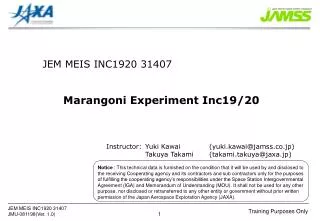
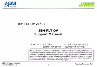
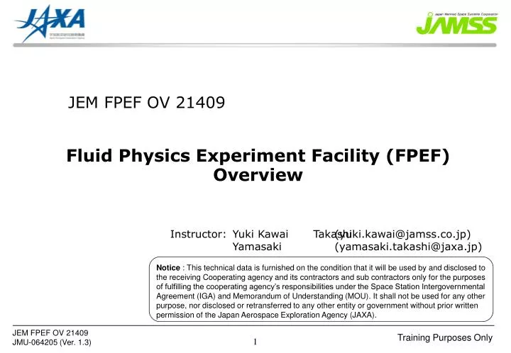
Notice : This technical data is furnished on the condition that it will be used by and disclosed to the receiving Cooperating agency and its contractors and sub contractors only for the purposes of fulfilling the cooperating agency’s responsibilities under the Space Station Intergovernmental Agreement (IGA) and Memorandum of Understanding (MOU). It shall not be used for any other purpose, nor disclosed or retransferred to any other entity or government without prior written permission of the Japan Aerospace Exploration Agency (JAXA). JEM FPEF OV 21409 Fluid Physics Experiment Facility (FPEF) Overview Instructor: Yuki Kawai Takashi Yamasaki (yuki.kawai@jamss.co.jp) (yamasaki.takashi@jaxa.jp)
Objectives After this lesson the trainee will be able to: • Purpose of FPEF • FPEF Interfaces • Functions and components of FPEF • Explain what kind of phenomenon can be observed by FPEF. • Explain the functions of Experiment Cell. • Explain how Gas Ar (GAr) will be supplied to/wasted from Experiment Cell. • List three observation equipments in FPEF. • Explain the function of Lamps. • Explain two functions of FPEF Control Equipment.
Lesson Outline Contents: - Purpose of FPEF - FPEF Interfaces - FPEF Major Architecture - FPEF Major Components - Interfaces in FPEF - Acronyms Appendix: - FPEF Specifications - Connectors/QDs Interfaces in FPEF Page 4 5 6 7 16 18 20 21
Heating disk (High Temp.) Lower Liquid Bridge Surface Tension Higher Cooling disk (Low Temp.) Purpose of the FPEF The main purpose of FPEF is to observe and measure Marangoni convection in the liquid bridge. FPEF Marangoni convection is driven by the difference of the liquid surface tension, and surface tension is higher at low temperature part than at high temperature part. FPEF is used in combination with Experiment Cell, and provides following capabilities. Experiment Cell Experiment Cell FPEF • Form the liquid bridge and generate Marangoni convection. • Observe and/or Measure Marangoni convection. • Accomodate Experiment Cell. • Observe/Measure Marangoni convection in three ways. • Control and measure temperature of Experiment Cell. • Provide resources to Experiment Cell. • Provide telescience operation and sequential control automation.
Power Water Avionics Air Video Gas Exhaust Gas Supply Communication FPEF Interfaces JEM System Ryutai rack FPEF Silicone Filter Main Power PDU-b2 PPDB FPEF MTL Moderate Temperature Water Loop IPU Avionics Air AAA/SD Experiment Cell PPDB AAA/SD Waste Gas Silicone Filter Waste Gas Line GAr Ryutai rack CGSE Video IPU Command/Telemetry PDH/JCP Parameter File (Command and Telemetry) PLT (Command, Telemetry and Parameter file) Ground Note: Interfaces among equipments in Ryutai Rack are not shown in this figure. PLT is not used in nominal operations.
FPEF Major Architecture FPEF Silicone Filter FPEF Experiment Cell Observation equipments 3-D Camera 2-D Camera Lamps and Fiber Optic Cables IR Imager Motor Driver Video Switcher Control Equipment Experiment Cell Front covers Experiment cover Cooling Water and Gas Line Front Cover Ryutai rack Experiment cover Silicone Filter
FPEF Major Components Experiment Cell • Experiment Cell contains experiment sample. • Experiment Cell has the heating disk and the cooling disk, forms liquid bridge, and creates temperature gradient between the disks. • The design of Experiment Cell depends on the experiment purpose. • - has unique observation/measurement system. • - has unique disk size. e.g. 30, 50 mm in diameter • - has unique sample. e.g. Silicone oil, small particles • Crew member assemble/disassemble Experiment Cell. • Crew exchange Experiment Cell/sample cassette. Installed to FPEF • Experiment Cell has Ar/waste gas, cooling water, power, communication and video interfaces with FPEF. Install to FPEF Experiment Cell FPEF Mechanical interfaces
FPEF Major Components (Cont’d) Experiment Cell (Cont’d) Connecters and QDs with FPEF Gas QD Heating disk Water QD Install to FPEF Liquid bridge Experiment Cell Heating disk Cooling disk Cooling disk
FPEF Major Components (Cont’d) Observation equipments diaphragm focus Crew will install IR Imager into FPEF CCD Camera (three) CCD Camera IR Imager Aux light IR Imager Power Harness 3-D Camera (FPEF GM) CCD Camera Mirror IR Imager Video Harness 2-D Camera
FPEF Major Components (Cont’d) Observation equipments (Cont’d) Mirror Case IR Imager measures surface temperature of liquid bridge. Heating disk side (transparent) 2-D Camera observes whole shape of liquid bridge. 3-D Camera Liquid bridge Cooling disk side observes small particles in liquid bridge by three CCD cameras. 3-D Camera also can move backward and forward according to depth of field.
FPEF Major Components (Cont’d) Lamps Motor Driver light liquid bridge inside of Experiment Cell through two Fiber Optic Cables. drives 3-D Camera and cooling disk in Experiment Cell. Lamp 1 Limit Switch When Experiment Front Cover is attached, Experiment can be conducted. Lamp 2 Video Switcher FPEF interface Experiment Cell interface receives video images from 2-D Camera, 3-D Camera, IR Imager, and Experiment Cell. Some of these images are switched and transferred to IPU. IR Imager video interface(input) Fiber Optic Cable (two) Experiment Cell video interfaces(input) IPU interfaces (5 channel) (output)
FPEF Major Components (Cont’d) Control Equipment Control Equipment provides following functions • - receives power from Ryutai rack PPDB and supplies power to components in FPEF and Experiment Cell. • - Communicates with Payload Data Handling Unit (PDH) and controls components in FPEF and Experiment Cell. Control Equipment Experiment Cell power/ signal interfaces Control Equipment IR Imager power interface Ground use only 1553B interface
FPEF Major Components (Cont’d) Front covers Operations Configuration Stowage Configuration IR Imager 1553B cable pass through IR Imager Experiment Cell Velcro Silicon Filter interface Experiment Cover Body Front Cover Experiment Cover Plate Experiment cover Front Cover - is used during experiment. - has 1553B cable pass through and Silicon Filter interface. - is used during launch and storage.
FPEF Major Components (Cont’d) Cooling Water and Gas Line - FPEF has cooling water line to cool down the Control Equipment and Experiment Cell. - FPEF provides Gas Ar supply and waste gas vent functions to replace the air inside of Experiment Cell by Ar gas. Fluid interfaces Cooling water interfaces for Experiment Cell Gas Ar supply interface to Experiment Cell Waste gas interface from Experiment Cell through Silicone Filter Fluid interfaces
FPEF Major Components (Cont’d) Experiment cover Silicone Filter Silicone Filter Unit Silicone Hose A QD - removes silicone oil vapor from waste gas from Experiment Cell. - is installed in the right side of FPEF. Rail for Silicone Cover Silicone Filter FPEF Silicone Filter Unit FPEF Silicone Hose A FPEF Silicone Hose B FPEF Silicone Cover A FPEF Silicone Cover B Bolts FPEF Silicone Filter Ryutai Rack (upper part) Experiment Cell GAr IN GAr OUT Silicone Filter Unit Silicone Hose A Silicone Hose B Silicone Cover A Silicone Cover B
Interfaces in FPEF Rear Side PPDB Fiber Optic Cable Fiber Optic Cable (to PDH) Experiment Cell ( uses some of these interfaces) Front Side
P Pt S S M M S Interfaces in FPEF (Cont’d) GRV2 GRV1 GPS1 SV1 GPR1 GOF1 GF1 Experiment Cell GAr Supply Line OD1/4” F Ar:0.5~0.79 MPa[73~114psia] GAr IN Low Pressure Middle Pressure GAr Line GAr Line Silicone Filter Unit SV2 GF2 Waste Gas Line OD1/4” F GAr OUT WA1 WV1 IN OD1/4” Cooling Water :0.69 Mpa(100[psia])(MAX) COOLANT WATER SUPPLY Differential Pressure : 33+0-1[kPa] WOF1 Cold plate Control Equipment PT1 COOLANT WATER RETURN WOF2 OUT OD1/4” Cooling Water Experiment Cell FPEF FPEF Rack Pt F P
AAACCDFPEFGArIPU IR MTLPDHPDUPLTPPDBSD Avionics Air AssemblyCharge Coupled DeviceFluid Physics Experiment FacilityGas ArgonImage Processing UnitInfrared Moderate Temperature LoopPayload Data Handling UnitPower Distribution UnitPayload Laptop TerminalPayload Power Distribution BoxSmoke Detector Acronyms
Appendix - FPEF Specifications - Connector Interface Part
FPEF Specifications Item Specifications Dimensions 1 / 4 Payload Drawer: W482×H621×D660mm 2-D Camera (Liquid Bridge Form Observation) CCD Camera (1ch) Lamp source; 15W×2, 60Hz 3-D Camera (3-D Flow Rate Measurement) CCD Camera (3ch) Lamp source; 15W×2, 60Hz IR Imager (Surface Temperature Measurement Equipment) Spectral response; 8~14μm Measurement range; 0~100℃ Time resolution; 30flames/sec User Interface -Analog/digital interface -Digital communication interface -Power interface -Video output interface -Gas/ cooling water interface -Motor drive interface
Connector and QDs Interfaces in FPEF POWER J01 (Exp Cell Motor I/F) LAMP 1, LAMP 2 VIDEO J620 (Exp Cell CCD Camera I/F) GAr IN TRANSFOMER POWER J10, DIGITAL I/O J11, TEMP SENSOR J12, HEATER POWER J13 COOLANT WATER SUPPLY GAr OUT COOLANT WATER RETURN IR IMAGER POWER J15 GROUND USE ONLY 1553B J301 IPU INTERFACE IR IMAGER VIDEO J08 VIDEO SYNCJ09 Front view of FPEF EXP CELL VIDEO J310