Download
1 / 18
210 likes | 641 Vues
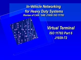
ISO 11783 Task Controller. Lecture 9 Task Controller – Part I ISO 11783 Part 10 BAE 5030 - 353 Spring 2009 Instructor: Marvin Stone Biosystems and Agricultural Engineering Oklahoma State University. Taken largely from: Andy Beck and Hans Nissen John Deere and Co.

E N D
ISO 11783 Task Controller Lecture 9 Task Controller – Part I ISO 11783 Part 10 BAE 5030 - 353 Spring 2009 Instructor: Marvin Stone Biosystems and Agricultural Engineering Oklahoma State University Taken largely from: Andy Beck and Hans Nissen John Deere and Co. NAIITF ISOBUS Task Controller Workshop 4 June 2008 BAE 5030-353
Purpose of Task Management • To allow management of • Machinery resources • Tractors • Implements • Combines • Sprayers • Etc • Labor resources Production inputs • Fertilizers • Seeds • etc • Production outputs • Grain • Hay • etc BAE 5030-353
Nature of task management • Task management facilities • Tasks can be defined and named • Tasks management actions are • Allocation or association of … with Tasks • Resources • Inputs • Outputs • Time of Allocation or association with Tasks • Before beginning task on desktop = Planning • At time of task on VT in the field = adhoc • Planned task data may be transported to the field and loaded into the task controller • Task data gathered in the field may be unloaded from the Task Controller and transported back to the desktop BAE 5030-353
Functionality covered by ISO 11783 Task Controller • Standardized Interface between the Mobile System and the Farm Management Information System (PC in farm office) • Standardized file format (XML based) between TC and FMS • Standardized communication between Task Controller (TC) and controllers on the bus (Process Data Message = PDM) • Documentation of work of the mobile system (totals of tractor, implements, time stamps, etc.; geo-referenced when GPS available) • Prescriptions for multiple implements in parallel • Handling of Coding Data (all kinds of setup data like operator names, farm and field names, machine information, etc.) • Handling of Machine Configuration (mounting positions including their position offsets, working width, etc.) • Data Dictionary (ISO11783 part 11) defines the data types (defined as online-dB on www.isobus.net) Andy Beck / Hans Nissen John Deere BAE 5030-353
Optional Task Controller Interface Methods Andy Beck / Hans Nissen John Deere BAE 5030-353
Task Management Workflow • Planning of field Task on the desktop computer (Farm Management Information System = FMIS) What, Where, How, by Whom, When, etc. • Conversion of task into standard XML format • Assignment of task data to “implements” (Working Sets clearly identified by their NAME) • Transfer from PC to Mobile TC (this may include a conversion) • TC transmits information as specified to “implement” controllers • TC collects information as specified in the field Totals, site specific data Logging, new Coding Data, etc • Transfer of data back to PC (this may includes conversion) • Analyzing of field data in FMIS BAE 5030-353
Task Controller User Interface Functions • A User-Interface is not mandatory, nevertheless common & useful to • Select a task from a list • Start/Stop a task • Modify a task • Create a task • Add new Coding Data • Display Warnings as needed • Provide Total Overviews • Etc. BAE 5030-353
TC – WS Message Interaction BAE 5030-353
Task Controller Connection Management • The Task Controller shall (must) on Startup: • Complete its correct Address Claim • Wait for 6 seconds after complete Address Claim • Start transmission of cyclic TC Status Message (initial status is ‘0’) • Allow WS to initialize and load their Device Configuration Data (DCD) • Parse the DCD on activation message and respond accordingly • Set the TC Status to ‘1’ when all needed settings are valid (task chosen and activated, all included WS connected, etc) BAE 5030-353
Working Set (WS) Connection Management • The Working Set shall (must) on Startup: • Complete its correct Address Claim • Wait for 6 seconds after complete Address Claim • Wait for TC Status Message • Identify itself and its members to the system • Start transmission of frequent WS Task Status Message • Query TC as to determine its capabilities • Request Language format • Query TC if DCD already exists (version etc) • Load DCD when not available or existing one doesn’t reflect the machine settings • Wait for TC feedback on DCD Activation Message BAE 5030-353
Task Controller Data Logging • The WS define in their DCD which elements can provide information for data logging • The Desktop SW usually defines which data to log for a certain operation (transferred in the XML task file as DataLogTriggers to the TC) • DataLogTriggers allow: • log a certain DDI from a certain DCD element of a specific WS • log specific Bits/Bytes from certain PGNs on the bus • log these data on certain intervals or thresholds (Trigger methods) • log cumulative total counters • Data can come in on different rates; special rules apply how the data gets logged in the binary data files send back to the PC. • Data is usually log with GPS position and time stamps • A Process Data Value can be send with a maximum of 10 times per second. BAE 5030-353
Task States BAE 5030-353
Task Controller Data Logging • System behavior on Start, Pause and Resume of a Task: • Start: • The TC sets the Task Status in its Status Message to ‘1’. • The WS sets all Total Counters to zero on the transition from ‘0’ to ‘1’. • The TC enables the Trigger Methods for the individual Process Data Variables as appropriate. • Pause: • The TC sets the Task Status in its Status message to ‘0’. • The WS stops increasing its total counters. • The WS stops sending its trigged data. • The TC requests from each WS each individual information marked as ‘counter’ in its DCD and stores them in the task file. • Resume: • Same as ‘Start’, but • TC restores the previously stored total counters in each WS BAE 5030-353
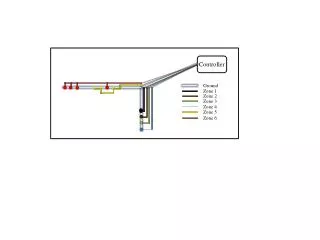
Task Controller Site-Specific Application • TC and WS may support prescriptions (WS defines e.g. its application rate as ‘set-able’ in its DCD) • Application map gets planned at Desktop PC • Application map gets attached to XML Task file as Grid or Shape File • TC opens application map in the field • TC determines the appropriate application rate based on GPS position in the application map • TC may takes offset of GPS to drop point into account (e.g. distance between GPS and Sprayer Boom) • TC sends the new application rate to the correct object of the connected WS • WS applies the new application rate when appropriate (e.g. Manual versus Auto Mode) • WS sends new current rate for documentation purpose BAE 5030-353
Prescription map terminology See ISO 11783 Figure 3 BAE 5030-353
Grid definition terminology See ISO 11783 Figure 4 BAE 5030-353