Download
1 / 23
230 likes | 318 Vues
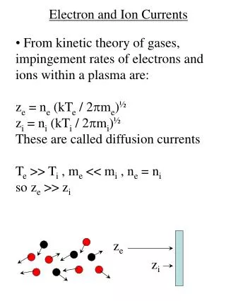
Polarized Electron Sources for Future Electron Ion Colliders M. Farkhondeh , Bill Franklin and E. Tsentalovich MIT-Bates accelerator Center Ilan Ben-Zvi , V. Litvinenko, Brookhaven National Laboratory PST05 Workshop, Tokyo, Japan, November 14-17, 2005. OUTLINE

E N D
Polarized Electron Sources for Future Electron Ion Colliders • M. Farkhondeh, Bill Franklin and E. Tsentalovich • MIT-Bates accelerator Center • Ilan Ben-Zvi , V. Litvinenko, • Brookhaven National Laboratory • PST05 Workshop, Tokyo, Japan, • November 14-17, 2005
OUTLINE • Electron Ion Colliders (EIC) • Current EIC designs (eRHIC and ELIC) • Polarized source for eRHIC • ring-ring design • linac-ring concept • Polarized RF gun • Polarized source for ELIC • Summary
EIC Kinematics range, a unique region Gluon momentum distribution measured EIC • High Ecm large range of x, Q2 Fixed target experiment • Lepton probe provides precision but requires high luminosity to be effective Nucleon spin structure studied Collider Electron Ion Collider
EIC in USA Currently two designs are under considerations: • At BNL and MIT: eRHIC an electron –Ion collider based on the existing RHIC accelerator at BNL. In 2004 produced a zeroth design report (ZDR). Electron ring design and polarized source by MIT-Bates. http://www.agsrhichome.bnl.gov/eRHIC/eRHIC_ZDR/ZDR_start.pdf • At Jefferson Lab: ELIC an Electron Light Ion Collider based on a 3-7 GeV ERL linac electron linac, a new electron circulator ring and a new light ion ring. http://casa.jlab.org/research/elic/elic.shtml
eRHIC Polarized electron and positron sources for storage mode of modest peak intensities required
Linac Ring Concept Very high intensity polarized source is required, I>100 mA
Ion Linac and pre - booster IR IR Snake Solenoid 3 - 7 GeV electrons 30 - 150 GeV light ions CEBAF with Energy Recovery Beam Dump ELIC Layout One accelerating & one decelerating pass through CEBAF (A=1-40) Ion Linac and pre Ion Linac and pre Electron Cooling - - booster booster Electron circulator ring IR IR IR IR Snake Snake Solenoid Solenoid 3 3 - - 7 GeV 7 GeV electrons electrons 30 30 - - 150 GeV (light) ions 150 GeV light ions Electron Injector CEBAF with Energy Recovery CEBAF with Energy Recovery Source requirements for ELIC less demanding with circulator ring. Beam Dump Beam Dump Thomas Jefferson National Accelerator Facility Operated by the Southeastern Universities Research Association for the U.S. Department Of Energy
360 Bunches 120 Bunches Ion ring Collider storage ring (eRHIC) Macroscopic Time structure for eRHIC 480 mA
Peak current requirements for eRHIC (ring-ring) • 450 mA average current in the ring and 120 bunches • 10 minutes fill time at 25 Hz injection 15000 pulse trains stacked bunches from the injector each 1.3 pC and ~70-100 ps wide (I=dQ/dt) • 18-20 mA peak current in linac • (instantaneous current within each bunch ) With QE of 5x10⁻⁴ , =800nm, would need ≥ 50 Watts of peak laser power.
Ring timing J-lab G0 laser: Ppeak=150 W Need > 50 W Polarized source options for eRHIC (ring-ring) Option 1: Modelocked laser Option 2: High power diode array laser • F_bunch~2-10, I_inj ~ 2-20 mA • Need work on the 102 MHz bunching. Bates laser system >120 W peak Time Bandwidth laser
Linac-ring Linac-Ring specification for the electron beam (based on an ERL-CW electron linac and RHIC) Beam rep-rate [MHz] 28.15 RMS normalized emittance [m] 5- 50 Bunch length at cathode [ps] 100-200 Electrons per bunch 1-10x·1010 Charge per bunch [nC] 1.6 -16 Average e-beam current [A] 0.45 Peak current [A] 135
A conceptual consideration by BNL ERL-FEL to produce KW of IR laser for Polarized source. Polarized Source for eRHIC linac-ring design Using scaling law from current J-lab charge/cm2 and an FEL laser, need to use a large area photocathode. No provision for positron source. Polarized source
Photocathode heat dissipation: (For Linac –ring photocathodes) 1 mm • With 0.5-2 kW laser power illuminating a 3 cm2 surface. • k= 0.75 W/cm.C for GaAs., 0.1 cm thick., • T = 20-80. Too much for an NEA surface with mono layer of Cs atoms. • With a molybdenum cathode stock, L=30 cm, S=0.5 cm2, T will be too high across the stock without active cooling. • Must have active cooling (flowing liquid or cold gas) to remove heat from photocathode and the cathode stock. • R&D for heat removal from cathode: • Design and construct actively cooled cathode • Test cathode assembly with cooling using high power diode lasers while monitoring the UHV conditions.
Cathode installed location Cathode retracted location Linear rail system Rail system adjustment Vacuum vessel Cathode installation cart Super conducting RF Gun, BNL and AES Ilan Ben-Zvi, V. Litvinenko BNL • Under construction at AES for the RHIC electron cooling. • GaAs based photocathode tests in this SRF gun may begin in 2 years (BNL, AES and MIT-Bates). • Also considered for ILC polarized source (FermiLab meeting, Nov 7, 2005. • Main issues: • base vacuum: UHV? • electron back- bombardment in an RF field
JLab FEL program with unpolarized beam ELIC with circulator ring Ave. Beam Current (mA) First low polarization, then high polarization at CEBAF Year Source requirements for ELIC less demanding with circulator ring. Few mA’s versus >> 100 mA for required for linac-ring. First polarized beam from GaAs photogun Continuing Trend Towards Higher Average Beam Current M. Poelker, EIC2 Workshop, 2004
Summary • EIC is required within a decade to maintain progress in the study of the fundamental structure of matter • partonic basis of atomic nuclei • spin structure of nucleon • An eRHIC ring-ring accelerator design has been developed based on realistic considerations with luminosity close to 1033 cm-2 s-1 . Storage ring reduces polarized source requirement for this option. Some R&D for polarized source is required and will be pursued at MIT-Bates. Polarized positrons based on self polarization in the ring is considered. • A more futuristic linac-ring eRHIC concept is also under consideration that requires very high intensity CW polarized source > 100 mA. An FEL based laser system is envisioned. Also, a superconducting polarized Rf gun may be considered for long term. • An ELIC design at J-Lab is under consideration based on a CW ERL-linac and a circulating ring. The circulating ring reduces the current requirement compared to a linac-ring design but complicates the time structure requirements. R&D in laser systems for this design at J-Lab is need.
Gun Issues for ELIC M. Poelker, EIC2004 Workshop • Need 80% polarized e-beam. • Use SVT superlattice photocathode. 1% QE at 780 nm; • ~ 1 W provides 1/e operation at 2.5 mA (if CW) • Commercial Ti-Sapp lasers with CW rep rates to 500 MHz provide 0.5 W. Homemade lasers provide ~ 2W. • Injector micropulse/macropulse time structure demands laser R&D. • 25 mA operation requires more laser power and/or QE. • Charge Limit? Yes, at 1.6 nC/bunch and low QE wafers. • Lifetime? Can benefit from further vacuum improvement • Gun HV ~ 500 kV to mitigate emittance growth. • Must limit field emission. R&D needed on all of the above areas.
Option 2: Ppeak=150 W CW-1 kHz Linac frequency F_bunch~2-10, e_cap~0.5 at Linac frequency I_inj ~ 2-20 mA Need work on the 102 MHz bunching.
J-lab G0 laser: Ppeak=150 W Time Bandwidth laser Option 1: For ring Iav =450 mA, need Ipeak=18 mA from injector Ppeak=50 W • Seems there is enough laser power. But need some R&D to test such lasers for this application. Surface charge limit and lifetime.
Source R&D at Bates using test beam setup • R&D on the eRHIC polarized source at Bates MIT-Bates 60 keV test beam setup Laser R&D for the two concepts of eRHIC injector