Download
1 / 18
200 likes | 466 Vues
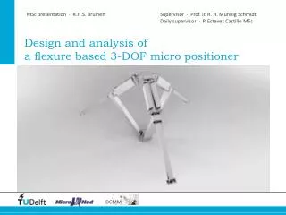
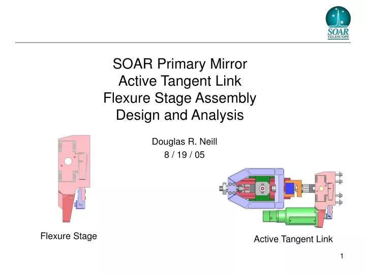
SOAR Primary Mirror Active Tangent Link Flexure Stage Assembly Design and Analysis. Douglas R. Neill 8 / 19 / 05. Flexure Stage. Active Tangent Link. Summary.

E N D
SOAR Primary Mirror Active Tangent Link Flexure Stage AssemblyDesign and Analysis Douglas R. Neill 8 / 19 / 05 Flexure Stage Active Tangent Link
Summary • If the flexure stage is produced from 440C stainless steel it will meet all the requirements, however, it will be difficult to manufacture this part with this material. • This material is difficult to machine. • This material utilizes quenching in the hardening process, which tends to distort flexures. It is also difficult to harden a thick part by quenching. • The acceptability of PH17-4 stainless steel for this application depends on the interpretation of the safety factors. If the safety factors are applied to the stress, this material does not meet the requirements. If the safety factors are applied to the load, the PH17-4 stainless steel flexure stage easily meets the requirements. This dilemma is the result of the majority of the stress resulting from the displacement induced deformation of the flexures. • As a result of the stiffness requirement, the flexure stage cannot be produced from titanium. The stiffness of the steel flexure stage of 1.03e6 in-lbs would be reduced to 5.3e6 in-lbs. It would not be possible to maintain the stiffness of the tangent link assembly to 3.0e6 in-lbs.
Flexure Stage Assembly 8x Translation Flexures 4x Flexure Shields Flexure Mount 2x Travel Limits Actuator Flexure Actuator Flexure Block 2x Lever Flexures Embedded Lever 4x 1/4 -28 SHCS
Flexure Dimensions: Flexure Stage Assembly Length: 0.335 in Width: 3.8 in Thickness: 0.025 in 16 Places Length: 0.585 in Width: 3.8 in Thickness: 0.080 in 8 Places Length: 0.50 in Width: 1.2 in (2x6in) Thickness: 0.030 in 1 Place Length: 0.50 in Width: 3.8 in Thickness: 0.040 in 2 Places
Flexure Stag Assembly: Various Views 10.025” 3.80” 3.63”
Top Level Requirements • Stroke Requirement: +/- 0.04 in (+/- 1.0mm) • Load Requirements: • Max Operational: 2,080 lbs • Design: 3,100 lbs • Resolution: 2.5 lbs • The maximum operating load is the maximum load that is expected during normal operation of the tangent links. • The design load is the required maximum producible force resulting from the actuator force and lever ratio. • To insure sufficient force is available to equate the link loads, the design load was set higher than the maximum expected operating load by a factor of 1.5.
Top Level Requirements • Minimum safety factors relative to the maximum expected operating load: • No Damage (yield) 2.5 • No Breakage (ultimate) 4.0 • The above no damage and no breakage requirements where equated to safety factors of 2.5 in yield and 4.0 in ultimate failure relative to the maximum expected operating load of 2,080 lbs. • Safety factors relative to the design load could have been utilized however, lower values would be utilized (~1.5 and ~2.5). Since the required operating load had not been determined at the start of this project, the safety factors relative to the maximum expected operating load were utilized.
Results Stress: Operational Load • The stress resulting from the maximum operational load of 2080 lbs was determined with the flexures of the flexure stage assembly in three different displacement orientations: • Maximum displacement: dz = +1.0 mm • No displacement: dz = 0.0 mm • Minimum displacement: dz = -1.0 mm • The majority of the stress is the result of the deformation of the flexures required to accommodate the displacement.
Results Stress: Operational Load Operating Load = 2080 lbs Displacement = +1 mm Maximum Stress = 69.2 K psi Operating Load = 2080 lbs Displacement = 0 mm Maximum Stress = 22.6 K psi Operating Load = 2080 lbs Displacement = -1 mm Maximum Stress = 68.4 K psi
Stress: Safety Factors and Margin of Safety(Stress Method) 440C Stainless Steel 17-4PH Stainless Steel
Stress: Safety Factors and Margin of Safety(Load Method) 440C 17-4PH
Analysis Buckling: Operational Load • Euler buckling is only a function of elastic modulus and not strength. Since all steels have similar elastic modulus, the buckling characteristics are insensitive to the type of steel used. • The buckling factor was determined relative to the maximum operational load. The buckling factor is the ratio of the expected buckling load to the applied load (maximum operational load). • The buckling factor was determined for the maximum operational load of 2080 lbs in conjunction with three different displacement orientations: • Maximum displacement: dz = +1.0 mm • No displacement: dz = 0.0 mm • Minimum displacement: dz = -1.0 mm
Analysis Buckling: Operational Load Operating Load = 2080 lbs Displacement = +1 mm Buckling Factor = 5.84 Operating Load = 2080 lbs Displacement = 0 mm Buckling Factor = 7.07 Operating Load = 2080 lbs Displacement = -1 mm Buckling Factor = 8.59
Results: Axial Stiffness • The stiffness of the flexure stage along the link axis, is determined by applying a unit force, in the negative z direction, to the link attachment location. • The FEA model is used to determine the displacement of the link attachment location, resulting from the unit force. • The stiffness, by definition, is the ratio of force to displacement. • Force: 1 lb • Displace: 9.7 e-7 in (at the link attachment point) • Stiffness: 1.03e6 lb/in Out of Date Modification Already Incorporated 1 Lb Link Attachment Location Stiffness Includes Effects of Actuator Stiffness of 2.3e5 lb/in
Results: Axial Stiffness • The flexure stage assembly stiffness value of 1.03e6 includes the effects of the actuator stiffness of 230,000 lb/in. • Although there are stiffness requirements for the entire link assembly, there are no specific requirements for the flexure stage. • Goal link assembly: 4.0 e5 lb/in • Requirement link assembly: 3.0 e5 lb/in • For series components, the stiffness of the link assembly is the result of the reciprocal addition of the stiffness of each component. The series stiffness combine in the same method as parallel electrical resistors. • For the combined stiffness to meet the 3.0 e5 lb/in requirement, each component must have a stiffness significantly larger than the required system stiffness. • Until the rest of the active tangent link assembly is designed and analyzed, it is not possible to conclude if the stiffness of the flexure stage assembly is adequate.
Results: Axial Stiffness • Since the majority of the flexure stage flexibility is from the lever, the stiffness can be increased by increasing the lever stiffness. This will, however, require an increase in the overall thickness of the flexure block by ~0.15 inches. • If the embedded lever stiffness is increased beyond this amount, the flexibility would be dominated by the actuator flexibility and minimal benefit would result. Out of Date Modification Already Incorporated Embedded Lever 0.15 in
Results: Load Capacity • 67 lbs of force are required to overcome the resistance of the flexures of the flexure stage at the maximum displacement of the actuator (+/- 0.04 in, 1mm). • This force must be removed from the available actuator force to determine maximum force that the flexure stage assembly can deliver. • Actuator force: 660 lbs • Flexure stage reaction: 67 lbs • Available force: 593 lbs • The available force is then multiplied by the lever ratio to determine the total force that the flexure stage assembly can produce. • Available force: 593 lbs • Lever ratio: 6.30 • Maximum force: 3,731 lbs • The maximum available force of 3,731 lbs is greater than the required value of 3,010 lbs.
Results: Force and Displacement Resolution • The LAH-80 actuator has a displacement resolution of 0.08um (3.1 u in) • The LAH-80 actuator combined with a 6.30 lever ratio will produce a displacement resolution of 0.0127 um (0.5 u in). • The system stiffness of the combined link assembly and structure is ~2.0 e5 lb/in. • The resulting force resolution is 0.0454 Kg (0.10 lb). • The force resolution of 0.10 lb is much greater than the minimum requirement of 2.5 lb.