Download
1 / 21
280 likes | 794 Vues
High Linearity Class B Power Amplifiers in GaN HEMT Technology. S. Xie, V. Paidi, R. Coffie, S. Keller, S. Heikman, A. Chini, U. Mishra, S. Long, M. Rodwell Department of Electrical and Computer Engineering, University of California, Santa Barbara .

E N D
High Linearity Class B Power Amplifiers in GaN HEMT Technology S. Xie, V. Paidi, R. Coffie, S. Keller, S. Heikman, A. Chini, U. Mishra, S. Long, M. Rodwell Department of Electrical and Computer Engineering, University of California, Santa Barbara Email: paidi@ece.ucsb.edu, sxie@engr.ucsb.edu Phone: (805)893-8044 Fax: (805)893-5705 2002 Topical Workshop on Power Amplifiers September 2002, UCSD
UCSB Outline S. Xie, V. Paidi • Introduction • How does Class B PA work? • Why single-ended Class B? • Highly linear single-ended Class B PA design and simulation • Measurement results • Conclusions
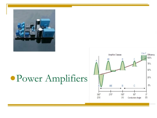
How does push-pull Class B PA work? VDS1 +Vin 0 0 -Vin VDS2 180 180 UCSB V. Paidi, S. Xie Vout = VDS1 – VDS2 Vin • Two identical devices working in 50% duty cycle with 180° phase shift. • Half sinusoidal drain current on each device, but full sinusoidal drain voltage. • Even harmonics are suppressed by symmetry => wide bandwidth (limited by the power combiner). • Class B: Ideal PAE 78.6%; feasible PAE 40-50% (typical GaN HEMT at X-band); Class A: Ideal PAE 50%, feasible PAE 20-30%.
Why not push-pull for RF MMIC UCSB V. Paidi, S. Xie To obtain high efficiency (78%), a half-sinusoidal current is needed at each drain. This requires an even-harmonic short. This can be achieved at HF/VHF frequencies with transformers or bandpass filters. However, • Most wideband microwave baluns can not provide effective short for even-mode. Efficiency is then poor. • They occupy a lot of expensive die area on MMIC.
Single-ended Class B = push-pull ID1 ID1 Vin +Vin 0 0 + -Vin ID2 -ID2 180 180 -Vin ID = ID Zero Z at 2fo Vin UCSB V. Paidi, S. Xie Push-pull Class B Even harmonics suppressed by symmetry Single-ended Class B with Bandpass filter Conclusion: From linearity point of view, push-pull and single-ended Class B with bandpass filter B are equivalent – same transfer function. Even harmonics suppressed by filter Bandwidth restriction < 2:1
Why is biasing critical for Class B? ID1 ID1 ID1 Vin Vin Vin + Vp + + Vp Vp ID2 ID2 ID2 Vin Vin Vin = ID = ID = ID Vin Vin Vin UCSB V. Paidi, S. Xie Ideal Class B Bias too low: Class C Bias too high: Class AB
Voltage Transfer Function as a Function of Bias Voltage UCSB V. Paidi, S. Xie Class AB, nonlinear Class B, linear Class C, nonlinear Class B is linear given that the current transfer function is linear
A source of IM3 distortion:Transconductance distortion UCSB V. Paidi, S. Xie Highly linear characteristics of GaN HEMT on SiC The third order term in the Taylor expansion is very small when biased at pinch off. Bias point The distortion will be minimum when the amplifier is biased at Class B by using GaN HEMT on SiC.
Single-ended Class B Power Amplifier UCSB S. Xie, V. Paidi • Lossy input matching network to increase the bandwidth • Cds is absorbed into the -section output lowpass filter - section lowpass filter Lossy input matching
Simulation performance of Class B UCSB S. Xie, V. Paidi Waveforms of drain voltage and current Simulation of class B amplifier @10GHz Saturated output power ~37 dBm Saturated PAE ~48% Class B bias: Saturated output power ~ 37 dBm, Saturated PAE ~ 48%
Simulation of Intermodulation Suppression and PAE @10GHz Class B bias: C/IMD3~44dBc PAE ~ 48% Class A bias C/IMD3~42dBc PAE ~ 35% Class AB bias Class C bias UCSB S. Xie, V. Paidi Best IM3 suppression is achieved at Class B and Class A
Device Performance of GaN HEMTs UCSB V. Paidi, S. Xie Performance of 12 fingers (1.2mm) device: • Lg ~ 0.25um • Idss ~ 1A/mm • ft ~ 55 GHz (~ 50 GHz for dual gate) • Vbr ~ 40V (~ 55V for dual gate) DC I_V curve RF Performance ~1.2 A Ft~55 GHz
UCSB Chip photograph of Class B power amplifier V. Paidi, S. Xie Gate 2 Gate 1 Source Air bridges Drain (Approximately 6mmX1.5mm)
UCSB Measurement setup S. Xie, V. Paidi Measurements: • Single tone from 4 GHz to 12 GHz; • Two-tone measurement at f1 = 8 GHz, f2 = 8.001 GHz; • Bias sweep: Class A (Vgs = -3.1V), Class B (Vgs = -5.1V, Class C (Vgs = - 5.5 V) and AB (Vgs = -4.5 V).
UCSB Class B power amplifier measurement result S. Xie, V. Paidi Gain vs. frequency Class AB Class B 3 dB bandwidth: 7GHz - 10GHz
UCSB Class B bias @Vgs = - 5.1V S. Xie, V. Paidi Single tone performance @ f0 = 8GHz: Saturated output power 36 dBm PAE (maximum) ~ 34% f1,f2 Two tone performance @ f1=8GHz, f2=8.001GHz : 2f1-f2, 2f2-f1 • Good IM3 performance: • 40dBc at Pin = 15 dBm, and • > 35 dBc for Pin < 17.5 dBm
UCSB Class A bias @Vgs = - 3.1V S. Xie, V. Paidi Single tone performance @ f0 = 8GHz: Saturated output power 36 dBm PAE (maximum) ~ 34% Two tone performance @ f1=8GHz, and f2=8.001GHz : f1,f2 Saturated output power each tone ~ 33dBm 2f1-f2, 2f2-f1 Good IM3 performance at low power level but becomes bad rapidly at high power levels
UCSB Summary of IM3 suppressions S. Xie, V. Paidi Class B Class A Class AB Psat Class C • Low output power levels (Pout < 24 dBm), Class A and Class B both exhibit good linearity (Class B > 36 dBc, Class A > 45 dBc). • Higher output power levels, Class A behaves almost the same as Class B. • Class AB and C exhibit more distortion compared to Class A and B.
UCSB Class B vs. Class A S. Xie, V. Paidi PAE of single tone IM3 suppression and PAE of two-tone Class A Class B Class A Class B While maintains the same IM3 suppression as Class A, Class B can get more than 10% of PAE.
Conclusions UCSB S. Xie, V. Paidi • For a less than octave bandwidth, a push-pull Class B amplifier can be replaced by a single-ended Class B amplifier with bandpass or lowpass filter. • A single-ended Class B MMIC power amplifier in GaN HEMT is designed and 36dBm of saturated power and 35dBc of IM3 suppression are obtained. • Class B is better than Class A because it can get good IM3 performance comparable to that of Class A, while providing PAE ~10% higher than that of Class A.
Acknowledgements UCSB S. Xie, V. Paidi This work was supported by the ONR under grant (N00014-00-1-0653) Special thanks to Dr. Walter Curtice, who provide us the C_FET3 model for simulation; Thanks to L.-Y. (Vicky) Chen and Likun Shen, who helped us for the measurement.