Download
1 / 17
170 likes | 325 Vues
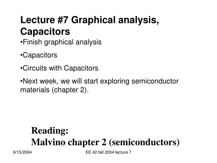
Lecture #7 Graphical analysis, Capacitors. Finish graphical analysis Capacitors Circuits with Capacitors Next week, we will start exploring semiconductor materials (chapter 2). Reading: Malvino chapter 2 (semiconductors). Power of Load-Line Method.

E N D
Lecture #7 Graphical analysis, Capacitors • Finish graphical analysis • Capacitors • Circuits with Capacitors • Next week, we will start exploring semiconductor materials (chapter 2). • Reading: Malvino chapter 2 (semiconductors) EE 42 fall 2004 lecture 7
Power of Load-Line Method We have a circuit containing a two-terminal non-linear element “NLE”, and some linear components. The entire linear part of the circuit can be replaced by an equivalent, for example the Thevenin equivalent. This equivalent circuit consists of a voltage source in series with a resistor. (Just like the example we just worked!). So if we replace the entire linear part of the circuit by its Thevenin equivalent our new circuit consists of (1) a non-linear element, and (2) a simple resistor and voltage source in series. If we are happy with the accuracy of graphical solutions, then we just graph the I vs V of the NLE and the I vs V of the resistor plus voltage source on the same axes. The intersection of the two graphs is the solution. (Just like the problem on page 6) EE 42 fall 2004 lecture 7
200K +- 2V ID D D Non-linear element NLE 1M + - 250K VDS 9mA +- S S The Load-Line Method We have a circuit containing a two-terminal non-linear element “NLE”, and some linear components. First replace the entire linear part of the circuit by its Thevenin equivalent (which is a resistor in series with a voltage source). We will learn how to do this in Lecture 11. Then define I and V at the NLE terminals (typically associated signs) 1V EE 42 fall 2004 lecture 7
ID D 200K 200K +- +- 2V 2V S ID ID (mA) D 10 NLE + - The solution ! VDS + - VDS S VDS (V) 1 2 Example of Load-Line method (con’t) Given the graphical properties of two terminal non-linear circuit (i.e. the graph of a two terminal device) And have this connected to a linear (Thévenin) circuit Whose I-V can also be graphed on the same axes (“load line”) The intersection gives circuit solution EE 42 fall 2004 lecture 7
ID D 200K +- 2V S ID (mA) 10 The solution ! VDS (V) 1 2 Load-Line method The method is graphical, and therefore approximate But if we use equations instead of graphs, it could be accurate It can also be use to find solutions to circuits with three terminal nonlinear devices (like transistors), which we will do in a later lecture EE 42 fall 2004 lecture 7
Power Calculation Review Power is calculated the same way for linear and non-linear elements and circuits. For any circuit or element the dc power is I X V and, if associated signs are used, represents heating (or charging) for positive power or extraction of energy for negative signs. For example in the last example the NLE has a power of +1V X 5mA or 5mW . It is absorbing power. The rest of the circuit has a power of - 1V X 5mA or - 5mW. It is delivering the 5mW to the NLE. So what it the power absorbed by the 200K resistor? Answer: I X V is + 5mA X (5mA X 200K) = 5mW. Then the voltage source must be supplying a total of 10mW. Can you show this? EE 42 fall 2004 lecture 7
Storing charge • If you try to store charge on a piece of metal, like a Van de Graaff generator, the work required to put more and more charge on the piece of metal gets very large, and thus the voltage gets high fast. + + + + + + + EE 42 fall 2004 lecture 7
Capacitor • If you want to store more charge, at less voltage, then you can put two plates of metal close together, and store positive charge on one, and negative charge on the other. - - - - - - - - - - - - - + + + + + + + + + + + + EE 42 fall 2004 lecture 7
Capacitance • The voltage is proportional to the charge which is stored on the plates • +Q on one • -Q on the other • Current is the flow of charge per unit time • Since charge is proportional to voltage, we define a proportionality constant C called the Capacitance EE 42 fall 2004 lecture 7
Capacitance of parallel plates • The bigger the area of two plates which are close together, the more charge they can hold for a given voltage (proportionally) • The further apart, the bigger the voltage is for the same charge. (also proportional) The variable ε is a property of the material, called the dielectric constant EE 42 fall 2004 lecture 7
Capacitors • A battery is a complex device, chemical reactions generate current (charges) as needed to maintain the voltage • A capacitor is a much simpler device, it just stores charge by keeping positive charges close to the negative charges on separate conductors • As charge is added, the repulsion and therefore the voltage increases • As charge is removed, the voltage drops EE 42 fall 2004 lecture 7
+ V CAPACITORS | ( C i(t) capacitance is defined by EE 42 fall 2004 lecture 7
V1 V2 | ( C2 C1 Ceq Equivalent to + + + i(t) i(t) | ( | ( Veq Clearly, CAPACITORS IN SERIES Equivalent capacitance defined by EE 42 fall 2004 lecture 7
+ | ( | ( C2 C1 i(t) V Equivalent capacitance defined by + | ( Ceq i(t) V(t) Clearly, CAPACITORS IN PARALLEL EE 42 fall 2004 lecture 7
Charging a Capacitor with a constant current + V(t) | ( C i EE 42 fall 2004 lecture 7
Discharging a Capacitor through a resistor + V(t) i R C i This is an elementary differential equation, whose solution is the exponential: Since: EE 42 fall 2004 lecture 7
Voltage vs time for an RC discharge Voltage Time EE 42 fall 2004 lecture 7