Download
1 / 9
90 likes | 278 Vues
GEM Design Plans. Jason Gilmore TAMU Workshop 1 Oct 2013. The CMS GEM project : Global Requirements on Electronics. Provide Trigger & Tracking data from all GE1/1 GEM Chambers. Design optimized for GEM detectors Use CERN common Projects where possible (GBTs & Versatile Link).

E N D
GEM Design Plans Jason Gilmore TAMU Workshop 1 Oct 2013
The CMS GEM project : Global Requirements on Electronics Provide Trigger & Tracking data from all GE1/1 GEM Chambers • Design optimized for GEM detectors • Use CERN common Projects where possible (GBTs & Versatile Link) • GEM detectors • Triggering • Tracking • Provide “Fast OR” trigger information with granularity of 2 or 4 channels to send locally to CSC TMB. • Timing resolution <8ns. • Provide full granularity tracking data on receipt of a L1A • Full resolution not available before L1A ? • Be compatible with CMS trigger upgrade possibilities • LV1A latency < 20us • LV1A rate < 1MHz Poisson
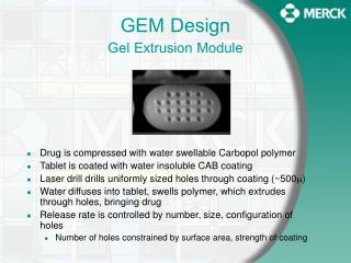
GEM Front-End Electronics Geometry GEMs are logically divided by columns in phi and partitions in eta • Each region is 128 strips wide • Read out with a VFAT3 chip VFAT3 chips • GEM hit location encoding: • Column (2 bits) • Partition (3-4 bits) • Trigger Pad ID (5-6 bits) • Total: 10-12 bits (most likely 10 bits) 6, 8, 10 partitions • GEM data to OTMB over 2 fiber links: • 96 bits/BX using DCFEB fiber protocol • Encode up to 9 GEM pad hits • Negligible probability to have more than 9 hits in a GEM chamber 3 columns
VFAT3 Front-End ChipSeparated Trigger & Tacking (STT) Fixed Latency trigger path: “S” bits Tracking path, After L1A This is the favorite architecture for CMS
Trig Unit Synchronous to LHC Bx, Reduced granularity to 2 or 4 strips (Example 1.2): (1 bit per 4 channels) Trigger granularity = 4 strips, Frequency = 320Mbps send 32 bits per Bx 7/8 bit encoding ? 5 slvds O/Ps = 35 bits / bx 1 bit for clock tick (sync) 2 bits spare Example 1: (1 bit per 2 channels) Trigger granularity = 2 strips, Frequency = 320Mbps send 64 bits per Bx 7/8 bit encoding ? 10 slvds O/Ps = 70 bits / bx 1 bit for clock tick (sync) 5 bits spare 1 bit per hit 1) (lossless) Example 2: Encode (7 bits) + next ch Trigger granularity = 1 strip, Max 8 hit channel addresses + neighbor Frequency = 320Mbps No 7/8 bit encoding 8slvds O/Ps = 80 bits / bx 1 slvds O/P for clock sync Example 2.2: Encode (6 bits) + next ch Trigger granularity = 2 strips, Max 8 hit channel addresses + neighbor Frequency = 320Mbps 7/8 bit encoding 8slvds O/Ps = 80 bits / bx 1 slvds O/P for clock sync 2) Channel address hit Neighbor hit (Can incur losses) Both require Data Concentrator ASIC or FPGA to : Gather Trigger signals from 24 VFAT3s Encode addresses of hits to include chip location Transmit to dedicated trigger GBT or optical Tx
Separated Trigger & Tracking Plan [Fixed Latency Trigger ASIC (FPGA)] 24 VFAT3 (STTP version) TRIGGER PATH Fixed Latency Trigger If granularity = 2 strips > 1536 addresses (11 bit address) If granularity = 4 strips > 768 addresses (10 bit address) Aim : Keep complexity of concentrator chip low VFAT3 STT Data PATH Full granularity (non zero suppressed) 1GBT for 8 VFATs “S” signals@ 320Mbps Concentrator & Encoding: FPGA 24*DataOut @ 320Mbps GBT GBT GBT GBT TMB Trig data (encoded S-bits) Bandwidth = 3.2Gbps uTCA
CMS GEM Electronics Overview Optical path to uTCA relies n GBT ASIC development • GBT readout • Direct e-link communication between front-ends and GBT • No Separate path for trigger. • Trigger path to external systems at uTCA level.
CMS GEM Electronics System Development GEM_PCB (CERN) Development underway VFAT3 under design Hybrid development underway GLIBs Common CERN development uTCA CMS standard for upgrades Development (ULB) Opto hybrid (ULB): Hardware design started Using CERN common Projects (GBTs & Versatile Link) & collaboration with TAMU & TAMUQ AMC13 from Boston Uni. Interface to CMS CAEN power supplies Initial prototype : Using VFAT2 + Opto hybrid (without GBT) + uTCA Final prototype : VFAT3 + Opto hybrid with GBT + uTCA ……. Under development ……. Foreseen for 2016
Prototype Development Plan ULB: Software communication to VFAT2 through uTCA VFAT2 uTCA 2nd q 13 30x30 TMB TMB TMB VFAT2 Erni to Erni To evaluate GEB (GEM Electronic Board), VFAT hybrid, cooling mechanics. uTCA uTCA uTCA 3rd q 13 Turbo VFAT2 Opto hybrid Optional step : Small uTCA setup, allows opto hybrid, uTCA and DAQ software development uTCA 4th q 13 Full size prototype VFAT2 Opto hybrid Full size setup, allows opto hybrid, uTCA, DAQ software and link to CSC TMB 3rd q 14 VFAT3 Opto hybrid 2 Optional step : If GBT project is delayed 3rd q 15 VFAT3 + Final Optohybrid with FPGA + GBT 3rd q 15 Final setup with VFAT3 and GBT